Motor vehicle door lock

A technology of motor vehicle door locks and lock forks, which is applied in the direction of locks in accident situations, can solve problems such as no longer valid, and achieve the effect of avoiding accidental opening

Active Publication Date: 2018-06-19
凯毅德汽车系统(常熟)有限公司
View PDF19 Cites 1 Cited by
  • Summary
  • Abstract
  • Description
  • Claims
  • Application Information

AI Technical Summary

Problems solved by technology

Due to the opening of the motor vehicle door due to the impact of the actuating lever system in the unlocked position of the locking element, safety devices usually in motor vehicle doors, such as side airbags, lateral impact protection, etc., are no longer effective

Method used


Image

  • Motor vehicle door lock
  • Motor vehicle door lock
  • Motor vehicle door lock

Examples


Embodiment Construction

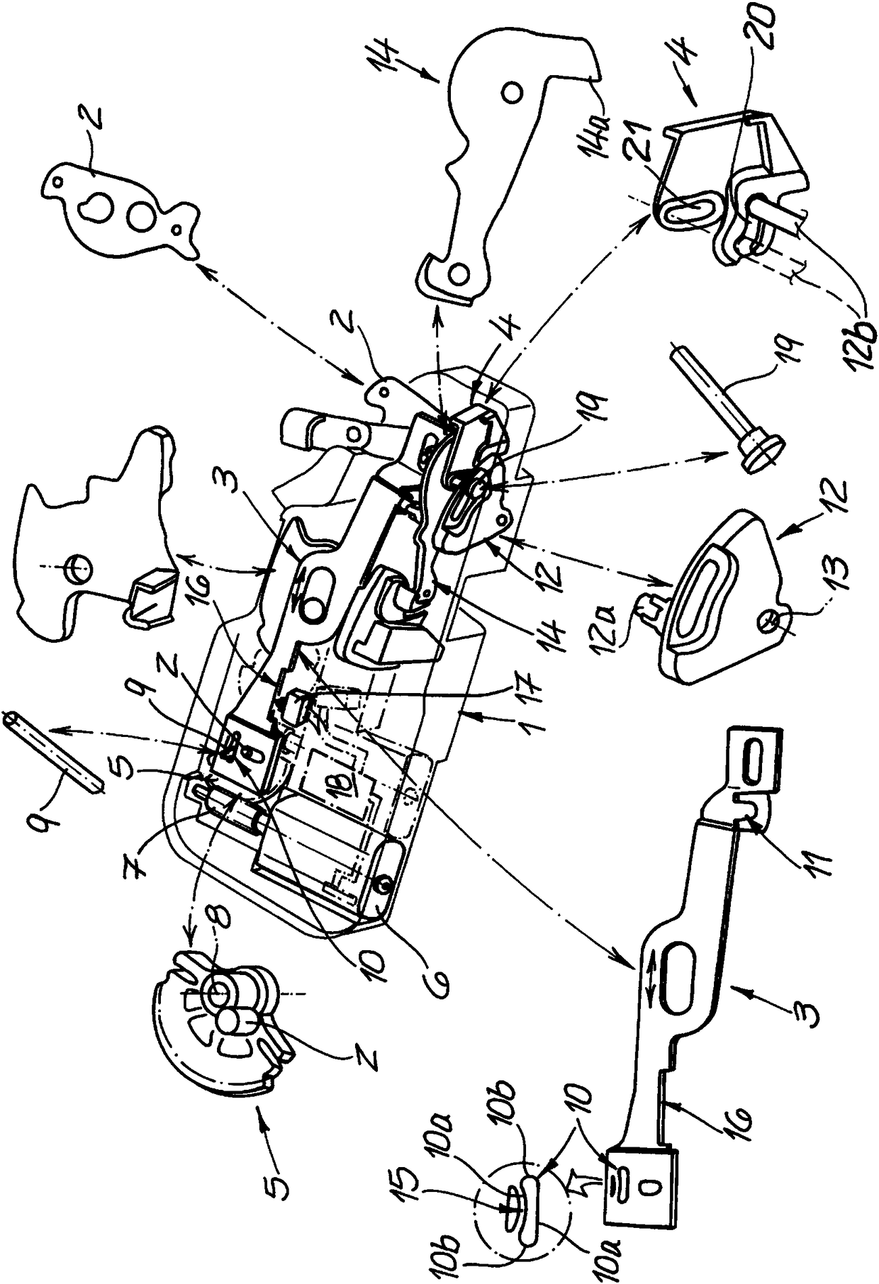
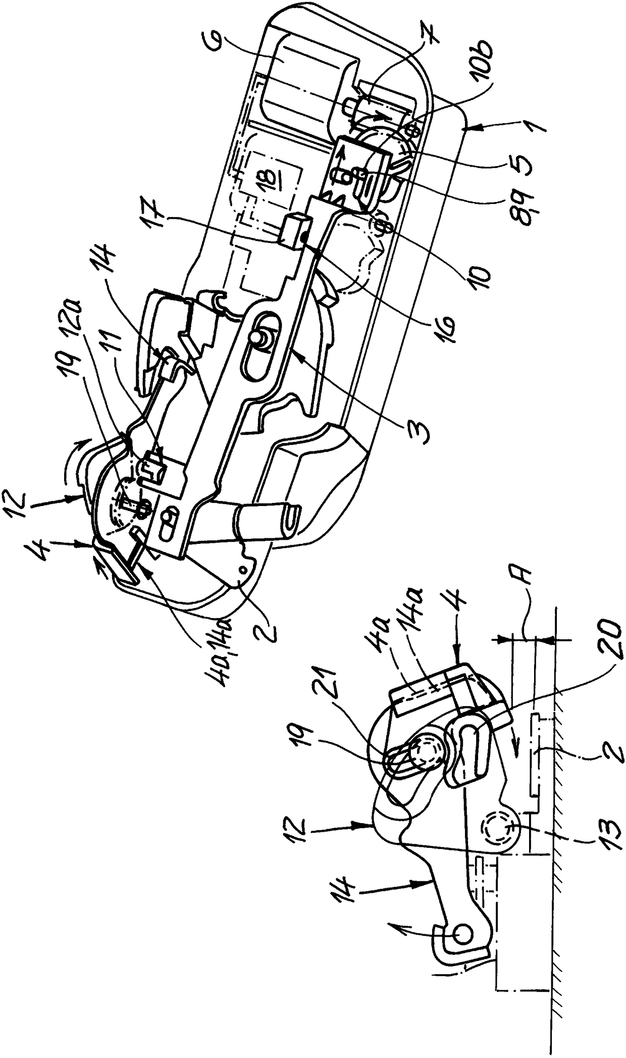
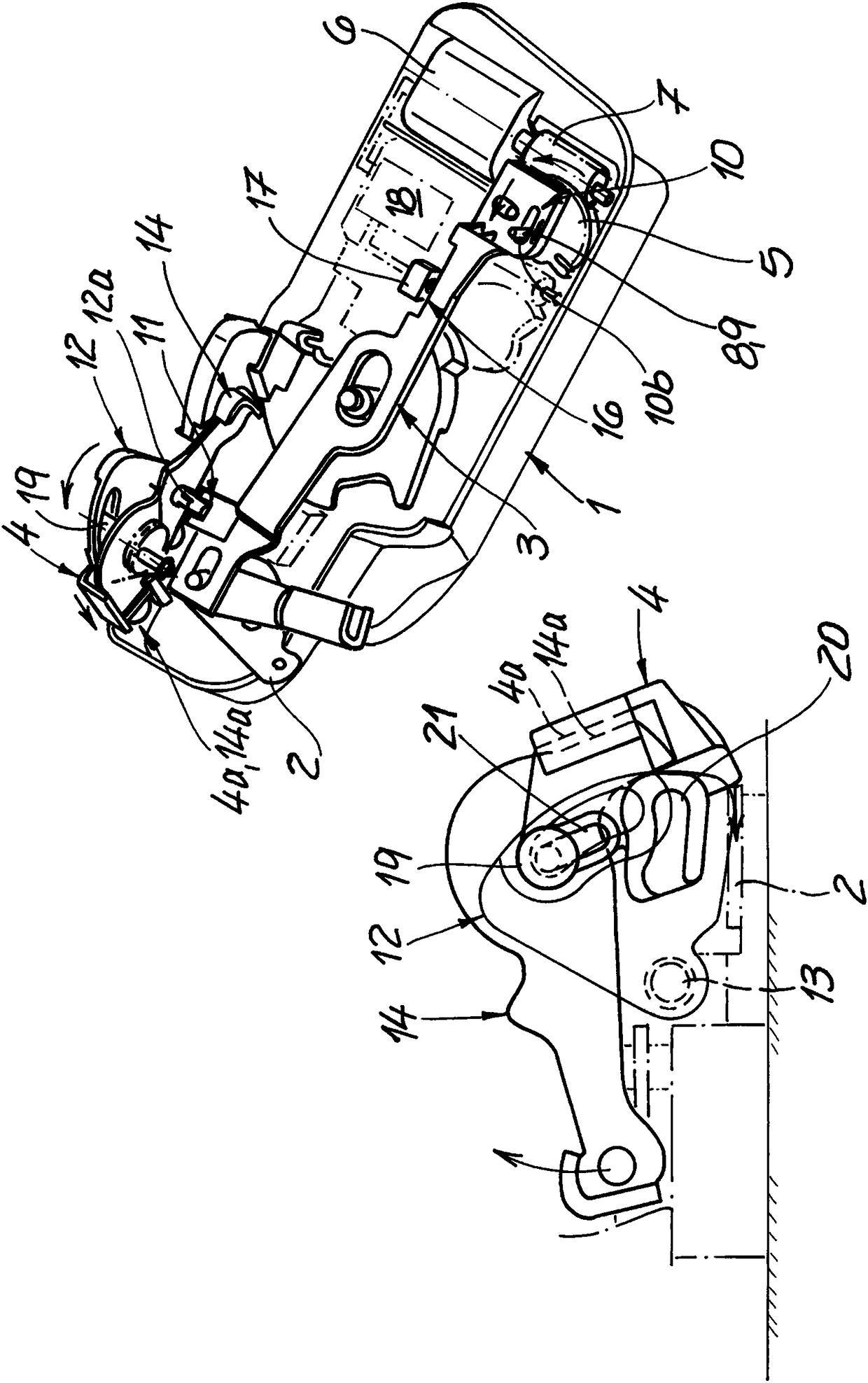
[0032] The drawing shows a motor vehicle door lock which is generally equipped with a locking mechanism (not shown), which essentially consists of a locking fork and a locking pawl. In practice, the locking mechanism is locked to the relevant motor vehicle door in the figure 1 The shown lock housing 1 is generally vertical in comparison. To strike the locking mechanism, the trigger lever 2 is arranged to lift the pawl away from the locking fork when the locking mechanism is closed and in the unlocked position. Thus, the locking fork can be opened by means of a spring. This is a common function for opening locking mechanisms as well as motor vehicle door locks.

[0033] Of particular importance to the invention is the locking element 3 , described in more detail below, which acts on the locking lever 4 . The locking element 3 is a transmission rod 3 which is largely linearly movable. The linear motion of the transmission rod 3 is figure 1 is shown by double arrows. The tr...


PUM


Abstract

The invention relates to a motor vehicle door lock. The motor vehicle door lock is provided with a locking mechanism mainly consisting of a lock fork and a lock jaw. In addition, the motor vehicle door lock is provided with at least one locking element (3) and driving devices (5, 6, 7) for the locking element (3). The locking element (3) is collided with a locking rod (4); and the locking rod guides an actuation rod (14) to a locking position not acted on the locking mechanism, and guides to a unlocking position mutually acted with the locking mechanism. The locking element (3) is acted on thelocking rod (4) by a rotating rod (12), so that the rotating rod (12) converts a linear motion of the locking element (3) to rotation of the locking rod (4).

Description

technical field [0001] The invention relates to a motor vehicle door lock with a locking structure, said locking mechanism essentially comprising a locking fork and a locking pawl, in addition at least one locking element and a drive for the locking element, wherein the locking element hits a locking lever, which in turn Steering the actuating lever to an inactive locked position relative to the locking mechanism and into an unlocked position interacting with the locking mechanism. Background technique [0002] Many designs of motor vehicle door locks with at least one locking element are known. Thus, the locking element can generally be a latch element or a central latch element as described in the prior art according to DE 195 30 726 A1 or US 5 802 894 A . In this case, the drive is designed as a latch drive or as a central latch drive. However, the locking element can also be designed as an anti-theft device or an anti-theft device element. The drive is then an immobil...

Claims


Application Information

Patent Timeline
Patent Type & Authority Applications(China)
IPC IPC(8): E05B77/04
Inventor 刘翔飞刘玉会杨波
Owner 凯毅德汽车系统(常熟)有限公司
Why Eureka
Try Eureka