
Solar cell panel frame

A solar panel and frame technology, which is applied in photovoltaic power generation, electrical components, photovoltaic modules, etc., can solve the problems of high frame line density, heavy frame weight, waste of resources, etc., achieve reduced frame line density, save frame profiles, save cost effect

Pending Publication Date: 2018-06-15
TONGWEI SOLAR HEFEI
View PDF4 Cites 0 Cited by
  • Summary
  • Abstract
  • Description
  • Claims
  • Application Information

AI Technical Summary

Problems solved by technology

[0002] In the prior art, the aluminum alloy profiles used to make solar photovoltaic cell frames follow the symmetrical cross-sectional structure of aluminum alloy profiles for doors and windows. What is different from vertically installed aluminum alloy doors and windows is that since the solar photovoltaic cell panels are installed in an inclined or horizontal manner, In order to meet the load-bearing capacity, the wall thickness has to be increased to increase the load-bearing strength, which also increases the cost, such as the aluminum alloy profile of a solar photovoltaic cell frame with the application number "201120219327.X", so there is a weight per unit length in the prior art The problems and deficiencies of large (that is, excessive linear density), high cost, and low bearing strength
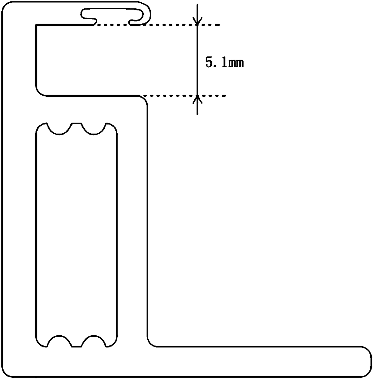
[0003] As attached to the manual figure 1 As shown, in the existing frame structure, the pitch of the slots used to install solar panels is 5.1 mm, and the linear density is 0.461 kg / m. Such a design structure obviously has the following defects: 1. The width of the slots is larger than The thickness of the battery module and the large amount of silica gel filling lead to an increase in the use of silica gel and a waste of resources; 2. In the case of sufficient load-bearing strength, the linear density of the frame is high, which makes the weight of the frame large, which cannot save the amount of profiles and greatly improves cost

Method used


Image

  • Solar cell panel frame
  • Solar cell panel frame
  • Solar cell panel frame

Examples


Embodiment Construction

[0019] The following will clearly and completely describe the technical solutions in the embodiments of the present invention with reference to the accompanying drawings in the embodiments of the present invention. Obviously, the described embodiments are only some, not all, embodiments of the present invention. Based on the embodiments of the present invention, all other embodiments obtained by persons of ordinary skill in the art without making creative efforts belong to the protection scope of the present invention.

[0020] see Figure 1-4 , the present invention provides a technical solution:

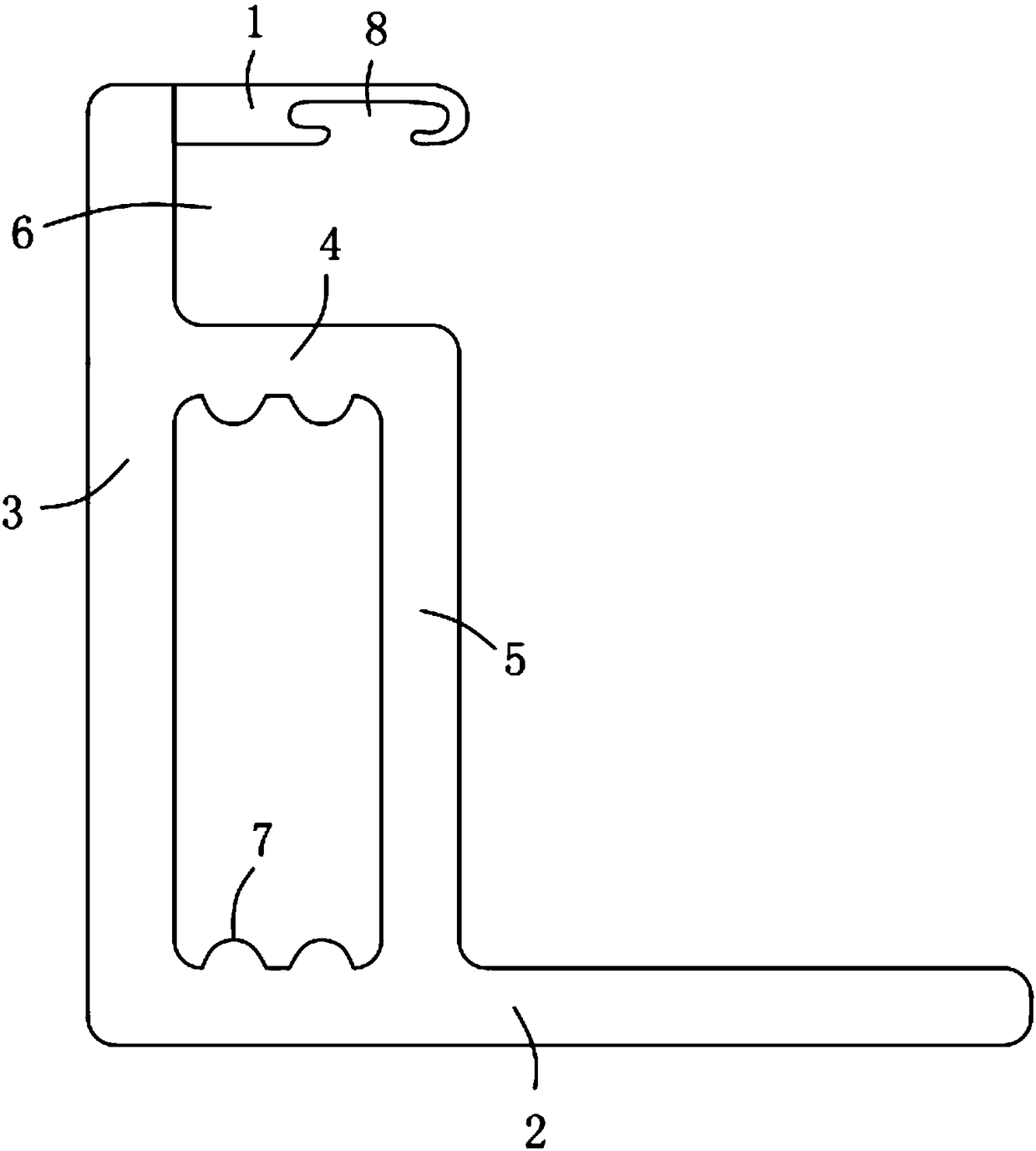
[0021] As attached to the manual figure 2 As shown, a solar cell panel frame, the frame is an asymmetrical cross-sectional structure composed of top side 1, bottom side 2, side side 3 and middle side 4, the linear density of the frame is 0.433kg / m, which can be Optimize the wall thickness and material consumption to adjust the linear density of the frame, thereby adjusting the w...


PUM


Abstract

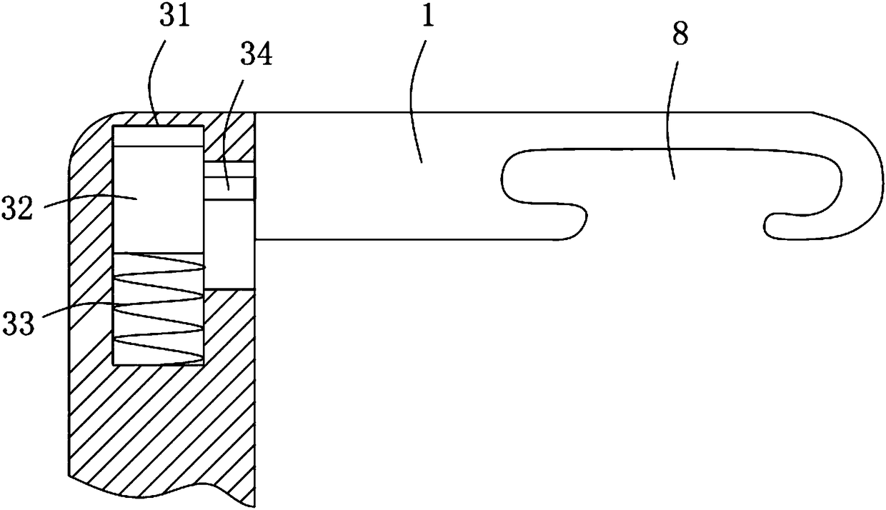
The invention discloses a solar cell panel frame of an asymmetric cross section structure composed of a top side, a bottom side, a lateral side and a middle side. The linear density of the frame is 0.433kg / m, the two ends of the lateral side are provided with the top side and the bottom side respectively, the bottom side is fixedly connected to the lateral side, the middle side is fixedly connected to the lateral side, a reinforcing side is fixed to the end, far from the lateral side, of the middle side, the end, far from the middle side, of the reinforcing side is fixed to the bottom side, and an area formed by the top side, the lateral side and the middle side forms a slot; and a chute is formed in the end, close to the top side, of the lateral side, a slide block is movably arranged inthe chute, the slide block is connected to the inner wall of the chute via a spring, and the slide block is fixedly connected to the top side via a connecting rod. Under the condition that the bearingintensity of the frame is not influenced, a method reducing the amount of silica gel and frame section bar is used, the cost is reduced greatly, the cell panel frame is optimized, and the frame is worthy of popularization.

Description

technical field [0001] The invention relates to the technical field of photovoltaic cells, in particular to a solar cell panel frame. Background technique [0002] In the prior art, the aluminum alloy profiles used to make solar photovoltaic cell frames follow the symmetrical cross-sectional structure of aluminum alloy profiles for doors and windows. What is different from vertically installed aluminum alloy doors and windows is that since the solar photovoltaic cell panels are installed in an inclined or horizontal manner, In order to meet the load-bearing capacity, the wall thickness has to be increased to increase the load-bearing strength, which also increases the cost, such as the aluminum alloy profile of a solar photovoltaic cell frame with the application number "201120219327.X", so there is a weight per unit length in the prior art The problems and deficiencies of large (that is, excessive linear density), high cost, and low bearing strength. [0003] As attached t...

Claims


Application Information

Patent Timeline
Patent Type & Authority Applications(China)
IPC IPC(8): H02S30/10
CPCH02S30/10Y02E10/50
Inventor 谢泰宏周丹谢毅张冠纶张忠文
Owner TONGWEI SOLAR HEFEI
Learn More