
A CT in situ analysis method of PBX damage evolution based on acoustic emission signals

An acoustic emission signal and damage evolution technology, which is applied in the use of wave/particle radiation for material analysis, analysis of materials, instruments, etc., can solve problems such as the inability to capture the initiation and propagation of microcracks, and the increase in experimental costs

Active Publication Date: 2019-03-12
XI AN JIAOTONG UNIV +1
View PDF6 Cites 0 Cited by
  • Summary
  • Abstract
  • Description
  • Claims
  • Application Information

AI Technical Summary

Problems solved by technology

On the one hand, the stress selection of CT scanning depends on experience, and the selection of scanning load nodes has no intuitive correspondence with the damage state of the material. The blind selection of scanning load nodes not only leads to an increase in the cost of the experiment, but also fails to capture the microcrack initiation and propagation process. ; on the other hand, the stress state of the specimen after unloading is very different from that during loading, and the crack shape after unloading is also different from that under loading

Method used


Image

  • A CT in situ analysis method of PBX damage evolution based on acoustic emission signals
  • A CT in situ analysis method of PBX damage evolution based on acoustic emission signals
  • A CT in situ analysis method of PBX damage evolution based on acoustic emission signals

Examples


Embodiment Construction

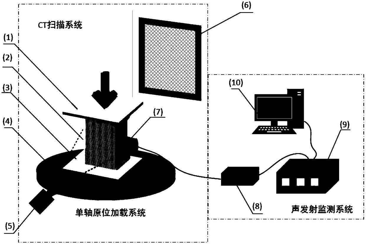
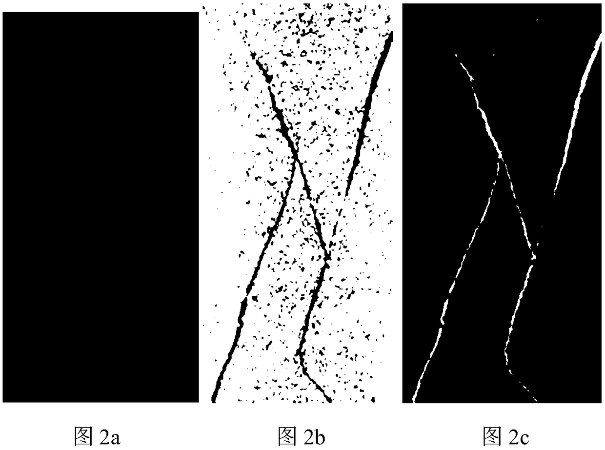
[0044] Such as figure 1 As shown, the detection steps of the method of the present invention are as follows: firstly build a CT in-situ loading and damage detection experimental system, which is composed of a single-axis in-situ loading system, a CT scanning system and an acoustic emission monitoring system; simultaneously implement mechanical loading and acoustic emission Signal acquisition, determine CT scanning load nodes according to the characteristics of acoustic emission signals, and collect CT images at different loading stages; extract the crack shape in CT scanning images, and perform three-dimensional visualization and quantitative analysis; combine material loading curves, acoustic emission signal characteristics, CT Image the three-dimensional features of cracks, and quantitatively describe the damage evolution of PBX specimen 2 during the loading process.

[0045] Combine below figure 1 , figure 2 , image 3 , Figure 4 The present invention is further descr...


PUM


Abstract

The invention discloses an acoustic emission signal-based PBX damage evolution CT in-situ analysis method. The method comprises building a CT in-situ loading and damage detection experimental system composed of a uniaxial in-situ loading system, a CT scanning system and an acoustic emission monitoring system, carrying out mechanical loading, acquiring an acoustic emission signal, determining CT scanning load nodes according to acoustic emission signal characteristics, acquiring CT images in different loading stages, extracting crack forms of the CT images, carrying out 3D visual and quantitative analysis, and quantitatively describing the damage evolution of the PBX material in loading according to a material loading curve, acoustic emission signal characteristics and the crack 3D characteristics of the CT images in different loading stages. The method combines the on-line monitoring of the acoustic emission technology, utilizes the CT in-situ observation method to realize quantitativedescription of damage evolution of the PBX material during loading, has the advantages of accurate capture of the initial point of the crack and visualization of the damage evolution process, is easyto realize and operate, has high efficiency and can be widely used for analysis of PBX material damage evolution.

Description

technical field [0001] The invention relates to the field of research on damage evolution of PBX materials, in particular to a CT in situ analysis method for PBX damage evolution based on acoustic emission signals. Background technique [0002] PBX (Polymer Bonded Explosive) is the abbreviation of polymer bonded explosive. Polymer bonded explosive is a particle-filled composite material bonded with high-energy explosive particles and high polymer binder as the main components. It is used in conventional weapons It is widely used in warheads and rocket propellants. In use, PBX not only bears complex structural loads, but also as an energetic material, it also needs to ensure good combustion and explosion functions. Therefore, PBX also plays an important role as a special functional material and a structural component. [0003] The service environment of PBX is very complex, and it is in different loading rates and stress states during production, processing, transportation, ...

Claims


Application Information

Patent Timeline
Patent Type & Authority Patents(China)
IPC IPC(8): G01N3/00G01N3/06G01N23/046
CPCG01N3/00G01N3/06G01N23/046G01N2203/0064G01N2203/0066G01N2203/0252G01N2203/0647G01N2203/0658
Inventor 解社娟许盼盼陈华陈洪恩陈振茂周海强张伟斌
Owner XI AN JIAOTONG UNIV
Learn More