Water cooling device applied to spinning heat roller

A water-cooling device and spinning technology, applied in household refrigeration devices, applications, household appliances, etc., can solve the problems of water pipe corrosion, shutdown, production cost increase, etc., and achieve the effect of reliable guarantee

Inactive Publication Date: 2018-06-15
SHANGHAI HAIDING IND DEV
View PDF4 Cites 3 Cited by
  • Summary
  • Abstract
  • Description
  • Claims
  • Application Information

AI Technical Summary

Problems solved by technology

Since the cooling water channel of the heat roller is very narrow, the cooling water needs to flow through it at high speed. When the water contains calcium and magnesium ions (ie hardness), the cooling water channel will be damaged due to the deposition of calcium magnesium carbonate (scale) for a long time. Gradually narrow until it becomes blocked; in addition, the acidity in the water will cause corrosion of the pipes, and the precipitation of insoluble substances in the water will also cause blockages in the pipes
The above various factors cause the water cooling pipeline to be unsmooth, which will eventually lead to major accidents such as overheating and burning of the guide wire hot roller, and shutdown of the whole line. In the chemical fiber industry, such accidents happen from time to time.
[0003] In view of the water quality problem, the German Oerlikon Textile Technology Company proposes that the pH value of the cooling water of the spinning hot roller is 8-8.5, and the use of slightly alkaline soft water as the cooling medium for the spinning hot roller can effectively eliminate the above disadvantages, but the soft water absorbs heat through the hot roller channel After raising the temperature, it cannot be returned to the hot roller for cooling. If it is discharged in large quantities, the production cost will be greatly increased, which is not advisable. Therefore, the process of using soft water repeatedly is very urgent.

Method used


Image

  • Water cooling device applied to spinning heat roller

Examples


Embodiment Construction

[0015] In order to better understand the technical solution of the present invention, it will be described in detail below through specific embodiments in conjunction with the accompanying drawings:

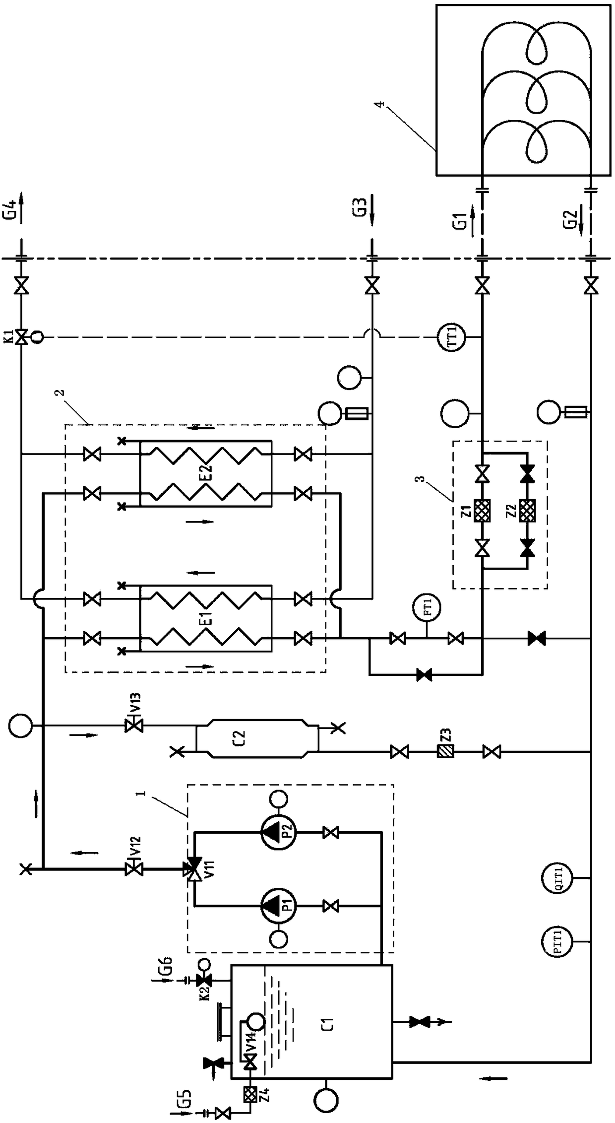
[0016] see figure 1 , a kind of water-cooling device that is applied to spinning heat roller of the present invention, comprises power pump group 1, heat exchanger group 2, softening water device C2, water storage tank C1, filtering device 3 and monitoring device;

[0017] The power pump group 1 includes a soft water pump P1, a soft water pump P2 and an automatic reversing valve V11, and the soft water pump P1 and the soft water pump P2 are connected to both sides of the automatic reversing valve V11. The soft water pump P1 and the soft water pump P2 maintain the circulation of the cooling liquid between the water cooling device and the spinning hot roller, and they are the standby working conditions for each other. The automatic switching valve V11 completes the regular automati...


PUM


Abstract

The invention discloses a water cooling device applied to a spinning heat roller. The water cooling device comprises a power pump group, a heat exchanger group, a soft water device, a water storage tank, a filtering device and a monitoring device. The power pump group, the heat exchanger group, the filtering device, the spinning heat roller and the water storage tank are connected in sequence to form a main circulation branch. The power pump group, the soft water device and the water storage tank are connected in sequence to form a softening treatment circulation branch. The monitoring deviceis used for monitoring the water quality. According to the water cooling device applied to the spinning heat roller, the spinning heat roller is cooled by the main circulation branch, water in a watercooling circulation system is softened by the softening treatment circulation branch, the water quality can be filtered through the filtering device in the system, meanwhile the water quality in thesystem is monitored in real time by the monitoring device, micro-alkaline soft water with the rated water quality, temperature and pressure can be stably provided for a heat roller cooling water way system, and a reliable guarantee is provided for the operation of the heat roller at the safe temperature.

Description

technical field [0001] The invention relates to a water cooling device applied to spinning hot rolls used in the textile field. Background technique [0002] The hot roller is the main machine of filament forming in the chemical fiber machinery, and the heat generated by the high-speed operation of 5000 rpm must be cooled and discharged at any time; the cooling medium is liquid, and generally uses constant pressure and quantitative flow water. Since the cooling water channel of the heat roller is very narrow, the cooling water needs to flow through it at high speed. When the water contains calcium and magnesium ions (ie hardness), the cooling water channel will be damaged due to the deposition of calcium magnesium carbonate (scale) for a long time. It gradually narrows until it becomes blocked; in addition, the acidity of the water will cause corrosion of the water pipe, and the precipitation of insoluble substances in the water in the pipe will also cause blockage. The abo...

Claims


Application Information

Patent Timeline
Patent Type & Authority Applications(China)
IPC IPC(8): F25D1/00C02F9/04
CPCC02F1/001C02F5/00F25D1/00
Inventor 陶勇夏前川陶正明
Owner SHANGHAI HAIDING IND DEV
Why Eureka
Try Eureka