
Internal combustion engine system

A technology of internal combustion engine and circulatory system, applied in the direction of internal combustion piston engine, combustion engine, mechanical equipment, etc., can solve the problems of limited working capacity of power turbine, unrecoverable energy, complicated matching between two-stage supercharging system and internal combustion engine, etc. The effect of high energy utilization rate and improved recycling rate

Inactive Publication Date: 2018-06-15
TSINGHUA UNIV
View PDF4 Cites 2 Cited by
  • Summary
  • Abstract
  • Description
  • Claims
  • Application Information

AI Technical Summary

Problems solved by technology

However, in this scheme, the exhaust gas discharged after passing through the turbine 2 still has a relatively high temperature, and part of the energy cannot be recovered, and the exhaust energy of the internal combustion engine is insufficiently utilized.
[0005] 2. Scheme two: In order to further utilize the exhaust gas energy discharged by the turbine 2 in the scheme one, the technical scheme of the prior art is to add a turbocharging system behind the turbocharger 2 on the basis of the scheme one, and adopt two-stage turbocharging technology, The two-stage turbo is used for intake boosting, but this solution is not suitable for situations where the power demand of the internal combustion engine is not large, and the matching of the two-stage supercharging system with the internal combustion engine is more complicated
Instead, on the basis of Scheme 1, the technology of adding a power turbine behind the turbine 2 is used to further recover the exhaust gas energy of the internal combustion engine, but this scheme requires that the gas pressure entering the power turbine is higher than atmospheric pressure, so when the exhaust gas entering the power turbine When the pressure is close to atmospheric pressure, the working ability of the power turbine is limited, and the exhaust gas energy of the internal combustion engine cannot be further recovered

Method used


Image

  • Internal combustion engine system
  • Internal combustion engine system
  • Internal combustion engine system

Examples


Embodiment 1

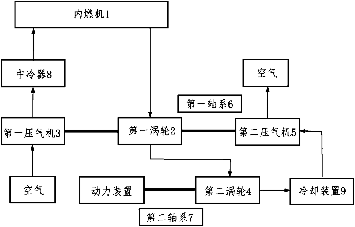
[0038] figure 2 It is a schematic composition diagram of the internal combustion engine system provided by Embodiment 1 of the present invention.

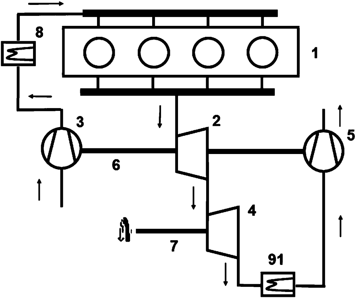
[0039] image 3 It is a schematic structural diagram of the internal combustion engine system provided by Embodiment 1 of the present invention.

[0040] Please refer to figure 2 , image 3 , The present invention provides an internal combustion engine system, comprising: an internal combustion engine 1 , a turbine 2 , a first compressor 3 , a second turbine 4 , a second compressor 5 , a first shafting 6 and a first shafting 7 .

[0041] An internal combustion engine 1 is provided with an intake port and an exhaust port. The internal combustion engine 1 is a kind of power machine, which burns fuel inside and directly converts the heat energy released by the fuel combustion into a heat engine for power.

[0042]The inlet of the first turbine 2 is connected to the exhaust port of the internal combustion engine 1 , and the outl...

Embodiment 2

[0059] Please refer to Figure 4 The difference between this embodiment and the first embodiment is that the cooling device 9 uses a thermoelectric conversion component 92 instead of the first heat exchange component 91 .

[0060] The inlet of the thermoelectric conversion component 92 is connected to the outlet of the second turbine 4 , and the outlet is connected to the inlet of the second compressor 5 for cooling the gas discharged from the second turbine 4 and converting the absorbed heat energy into electrical energy for output.

[0061] Optionally, the material of the thermoelectric conversion component 92 is a thermoelectric material, which is a material that can convert thermal energy into electrical energy.

[0062] Specifically, after the exhaust gas discharged from the internal combustion engine 1 is expanded to perform work by the second turbine 4, it still has a relatively high temperature, and there is room for waste heat recovery and utilization. The exhaust ga...

Embodiment 3

[0065] Because in the technical solution of Embodiment 1, the first heat exchange component 91 absorbs the heat of the exhaust gas, the purpose of reducing the temperature of the exhaust gas can be achieved, but no matter whether the first heat exchange component 91 adopts an air-cooled or water-cooled heat exchanger, This part of the heat is not recycled, but dissipated into the atmosphere. Therefore, in this embodiment, the Rankine cycle system is used to replace the first heat exchange component 91 , and the heat absorbed by the second heat exchange component 93 is further recycled to improve the utilization rate of energy.

[0066] Please refer to Figure 5 , In this embodiment, the Rankine cycle system includes a second heat exchange component 93 , a steam turbine 94 , a third heat exchange component 95 , a pump 96 and a third shaft system 97 .

[0067] The first inlet of the second heat exchange component 93 is connected to the outlet of the second turbine 4 , and the f...


PUM


Abstract

The invention discloses an internal combustion engine system, and belongs to the technical field of internal combustion engines. The internal combustion engine system comprises an internal combustionengine (1), a first turbine (2), a first air compressor (3), a second turbine (4), and a second air compressor (5), wherein an air inlet and an air outlet are formed in the internal combustion engine(1); an inlet of the first turbine (2) communicates with the air outlet of the internal combustion engine (1), an inlet of the first air compressor (3) communicates with the atmosphere, an outlet of the first air compressor (3) communicates with the air inlet of the internal combustion engine (1), an inlet of the second turbine (4) communicates with an outlet of the first turbine (2), an inlet ofthe second air compressor (5) communicates with an outlet of the second turbine (4), an outlet of the second air compressor (5) communicates with the atmosphere, the first turbine (2) is coaxially connected to the first air compressor (3) and the second air compressor (5) through a first shaft system (6) and is used for driving the first air compressor (3) and the second air compressor (5) to rotate so as to apply work, and the second turbine (4) outputs power through a second shaft system (7). According to the internal combustion engine system, one turbine is adopted to drive the two air compressors to rotate, the other turbine carries out power output, comprehensive recovery and utilization of energy of exhaust gas are carried out by utilizing reverse Brayton cycle, and meanwhile, air inlet supercharging of the internal combustion engine is taken into consideration so that the energy utilization rate of the whole system can be higher.

Description

technical field [0001] The invention relates to the technical field of internal combustion engines, in particular to an internal combustion engine system. Background technique [0002] Internal combustion engines play a very important role in national production and life. At present, the vast majority of vehicles and ships are powered by internal combustion engines. The internal combustion engine consumes a large amount of fossil fuels, but on average only 30%-40% of the energy is converted into mechanical energy, and nearly 60%-70% of the energy is dissipated into the atmosphere in the form of heat transfer during the working process of the internal combustion engine. Among them, the exhaust gas energy emitted by the internal combustion engine accounts for about 30% of the total energy. That is to say, the energy actually utilized by the internal combustion engine is in the same proportion as the exhaust gas energy emitted, which causes a great waste of energy. Recycling...

Claims


Application Information

Patent Timeline
Patent Type & Authority Applications(China)
IPC IPC(8): F01N5/02F01N5/04F01N13/08F02B37/013F01K25/08
CPCF01K25/08F01N5/025F01N5/04F01N13/08F02B37/013Y02T10/12
Inventor 郑新前张美杰林韵王钧莹曾翰轩
Owner TSINGHUA UNIV
Learn More