
Worktable capable of adjusting lifting

A workbench and table top technology, applied in the field of mechanical devices, can solve problems such as inability to lift, inconvenient for staff, troublesome adjustment process, etc., to achieve the effect of facilitating work, improving practical applicability, and enhancing structural stability

Pending Publication Date: 2018-06-15
ANHUI UNIVERSITY OF TECHNOLOGY AND SCIENCE
View PDF7 Cites 15 Cited by
  • Summary
  • Abstract
  • Description
  • Claims
  • Application Information

AI Technical Summary

Benefits of technology

This technology allows for easy manipulation by operators during lifts without having to manually lift or move heavy objects like tables. It uses electrical motors attached to a mechanism called a winch system where two rods are used together instead of one rope. When there's no motion being done, they keep moving smoothly due to their own weight. Once activated, these systems automatically elevate the table top panels based upon predetermined criteria such as speed and direction.

Problems solved by technology

The technical problem addressed by this patented solution relates to improving the usability and flexibility of tools used during production or assembling operations while ensuring efficient use with various levels of workers' ability. This includes moving tables between high-tooled positions when they shouldn’t, allowing employees to easily move from one level into another without having to stop doing their job altogether. Additionally, these solutions allow for manual adjustments based on factors like how tall an employee needs to stand compared to what he should have at home (their average sitting position).

Method used


Image

  • Worktable capable of adjusting lifting
  • Worktable capable of adjusting lifting

Examples


specific Embodiment approach

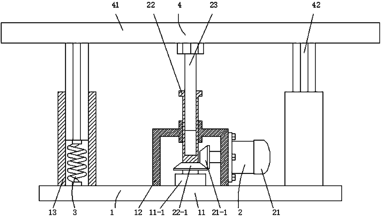
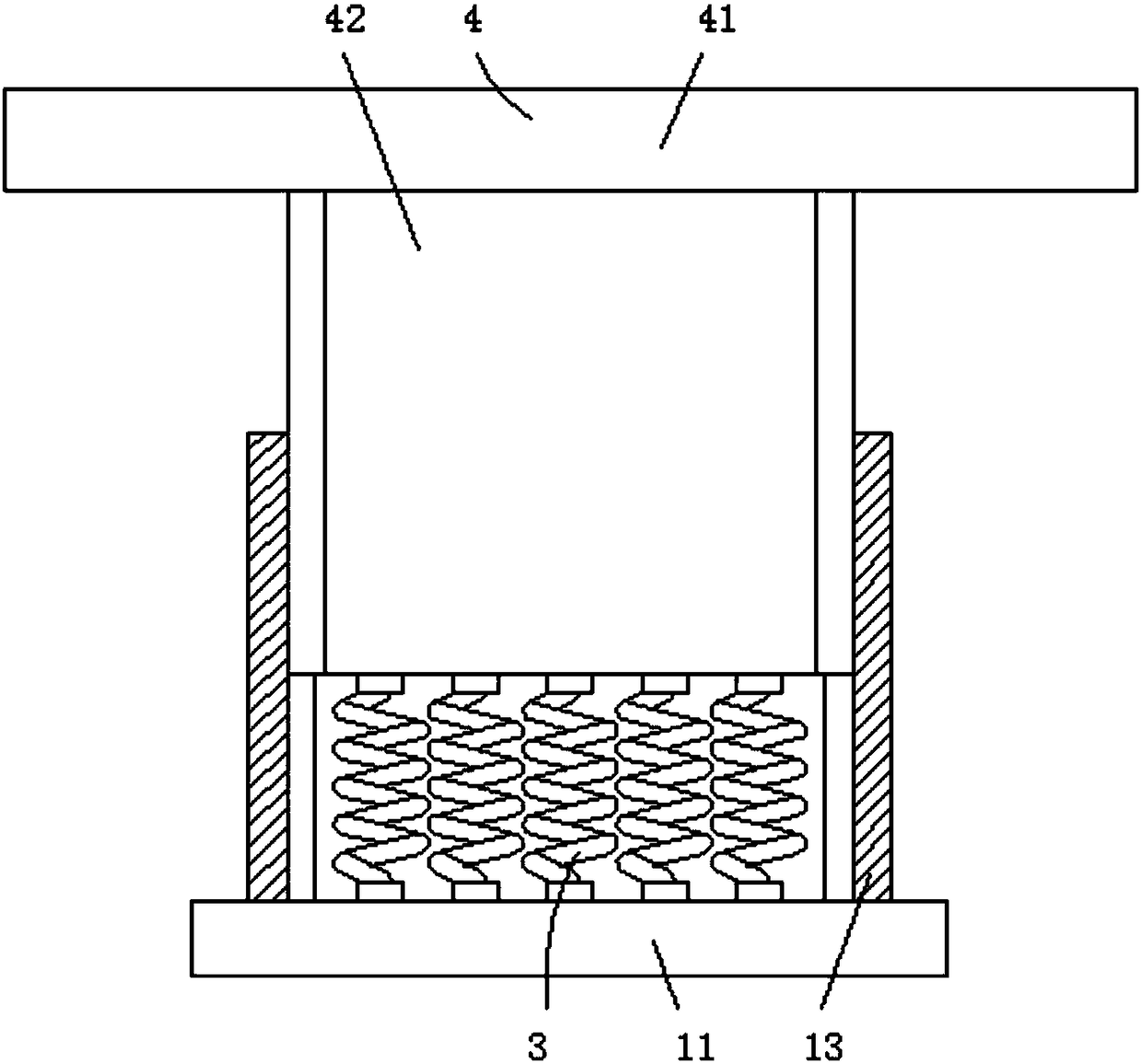
[0012] figure 1 and figure 2 The specific embodiment of the present invention is shown: a lifting and adjustable workbench, including a base assembly 1, a lifting mechanism 2, a spring 3 and a table assembly 4, the base assembly 1 includes a bottom plate 11, a transmission box 12 and a sliding guide column 13, The transmission box 12 is fixedly installed in the center of the base plate 11, and the sliding guide column 13 is provided with two, all fixedly mounted on the base plate 11, and symmetrically distributed relative to the central axis of the base plate 11, and the lifting mechanism 2 is composed of a motor 21 and The internal thread sleeve rod 22 is composed of, the motor 21 is fixedly installed on the side end of the transmission box 12, the output shaft of the motor 21 is connected with the side end of the transmission box 12 in rotation, and the output shaft end of the motor 21 is fixedly equipped with a drive Bevel gear 21-1, the internal thread sleeve rod 22 is r...


PUM


Abstract

The invention discloses a worktable capable of adjusting lifting, and relates to the field of mechanical devices. The worktable comprises a base assembly, a lifting mechanism, springs and a table assembly, wherein the base assembly comprises a bottom plate, a transmission box and sliding guide plate columns, the transmission box is fixedly arranged at the center of the bottom plate, the number ofthe sliding guide columns is two, the lifting mechanism comprises a motor and an internal threaded loop bar, the motor is fixedly arranged on a side end of the transmission box, the output shaft of the motor is transmittedly connected to the side end of the transmission box, the output shaft end of the motor is fixedly provided with a driving bevel gear, the internal threaded loop bar is rotatablyconnected with the bottom plate and the transmission box, the internal threaded loop bar is fixedly provided with a driven bevel gear, the driven bevel gear is meshed with the driving bevel gear, a screw rod is threadedly connected with the internal threaded loop bar, the number of the springs is ten, the table assembly is fixedly connected with the springs, and is slidably connected with the sliding guide plate columns, and the screw rod is rotatably connected with the table assembly; the worktable capable of adjusting lifting can be electrically and automatically lifted, thereby improving the practical applicability of the worktable.

Description


Claims


Application Information

Patent Timeline
Owner ANHUI UNIVERSITY OF TECHNOLOGY AND SCIENCE
Learn More