Two-stage screw compressor and compression method

A screw compressor, screw technology, applied in the field of compressors, to achieve the effect of easy disassembly, reduce the risk of gas and water leakage, and avoid mechanical loss

Active Publication Date: 2018-06-12
HANGZHOU JIUYI MACHINERY
View PDF9 Cites 9 Cited by
  • Summary
  • Abstract
  • Description
  • Claims
  • Application Information

AI Technical Summary

Problems solved by technology

[0005] The purpose of the present invention is to overcome the above-mentioned deficiencies in the prior art, and provide a two-stage screw compressor and compression method with reasonable structure design, scientific layout, and convenient use, which can solve the problems existing in the existing two-stage screw compressor

Method used


Image

  • Two-stage screw compressor and compression method
  • Two-stage screw compressor and compression method
  • Two-stage screw compressor and compression method

Examples


Embodiment Construction

[0018] The present invention will be further described in detail with reference to the accompanying drawings and embodiments. The following embodiments are for explaining the present invention and the present invention is not limited to the following embodiments.

[0019] Examples.

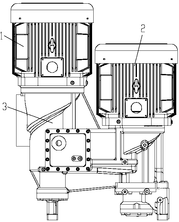
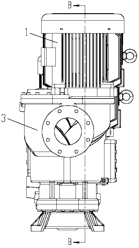
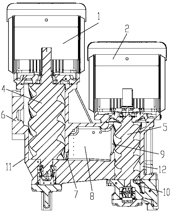
[0020] See Figure 1 to Figure 3 The two-stage screw compressor in this embodiment includes a main engine 3, a low-pressure stage drive 1 and a high-pressure stage drive 2. The two-stage screw compressor adopts a vertical structure, and the low-pressure stage drive 1 and the high-pressure stage drive 2 are both located above the main engine 3. , That is, the driver is on the top and the host 3 is on the bottom.

[0021] The host 3 in this embodiment includes a low-pressure stage housing 11, a high-pressure stage housing 12, a low-pressure stage screw 4 for first-stage compression of gas, and a stage for cooling the gas after the first-stage compression. The intermediate passage 8 and the high-pressure ...


PUM


Abstract

The invention relates to a two-stage screw compressor and a compression method. Most of screw compressors use traditional horizontal swinging, gear transmission and other structures, and are poor in performance. The two-stage screw compressor comprises a main machine and is characterized by further comprising a low-pressure-stage driver and a high-pressure-stage driver; the main machine comprisesa low-pressure-stage shell, a high-pressure-stage shell, a low-pressure-stage screw, an inter-stage channel and a high-pressure-stage screw; the low-pressure-stage shell is provided with an air inletcavity and a low-pressure-stage air outlet, the low-pressure-stage screw is installed in the low-pressure-stage shell, and the low-pressure-stage driver is directly connected with the low-pressure-stage screw; the high-pressure-stage shell is provided with a high-pressure-stage air inlet and a high-pressure-stage air outlet, the high-pressure-stage screw is installed in the high-pressure-stage shell, and the high-pressure-stage driver is directly connected with the high-pressure-stage screw; the two ends of the inter-stage channel are fixed to the low-pressure-stage shell and the high-pressure-stage shell respectively, the two ends of the inter-stage channel are communicated with the low-pressure-stage air outlet and the high-pressure-pressure air inlet respectively, and an injection holeis formed in the inter-stage channel. The compressor is reasonable in structural design, scientific in layout and convenient to use.

Description

Technical field [0001] The invention relates to a two-stage screw compressor and a compression method, belonging to the technical field of compressors. Background technique [0002] Compressors mainly provide original power for industrial production, including air compressors, process compressors, refrigerant compressors, etc. They are used in industrial automation, traffic braking, energy and chemical industries, refrigeration and air conditioning, etc., and are essential for modern industry Of equipment. Compressors consume a large amount of energy during operation and account for a large proportion of industrial energy consumption. For example, the power consumption cost of air compressors in the textile industry has accounted for about 30% of the industry cost. Therefore, the innovation and application of compressor energy-efficient technologies The promotion of national energy conservation and emission reduction projects is closely related to the creation of corporate profi...

Claims


Application Information

Patent Timeline
Patent Type & Authority Applications(China)
IPC IPC(8): F04C18/16F04C23/00F04C23/02F04C29/04F04C29/12
CPCF04C18/16F04C23/001F04C23/02F04C29/042F04C29/12F01C21/007F04C23/008
Inventor 丁小川徐晓明俞育飞周高明
Owner HANGZHOU JIUYI MACHINERY
Why Eureka
Try Eureka