Reciprocating type vibratory forced ramming hammer

A reciprocating, rammer technology, applied in the field of soft foundation treatment in the civil engineering industry, can solve the problems of foundation soil structure damage, no multi-level vibration effect, unfavorable pore water removal, etc., to reduce the number of times of ramming, increase the unit Sub-strong compaction, anti-damage effect

Active Publication Date: 2018-06-12
WUHAN NANFANG XUYU TECH ENG CO LTD
View PDF18 Cites 4 Cited by
  • Summary
  • Abstract
  • Description
  • Claims
  • Application Information

AI Technical Summary

Problems solved by technology

[0003] Traditional dynamic ramming hammers are divided into filling hammers, combined hammers, and cast iron hammers. One lift can only achieve one tamping impact. There is no multi-level vibration effect, which is not conducive to the removal of pore water. Although the tamping energy is relatively large, it is easy to cause foundation soil structure. destroy

Method used


Image

  • Reciprocating type vibratory forced ramming hammer
  • Reciprocating type vibratory forced ramming hammer
  • Reciprocating type vibratory forced ramming hammer

Examples


Embodiment Construction

[0015] Embodiments of the present invention will be described in detail below in conjunction with the accompanying drawings.

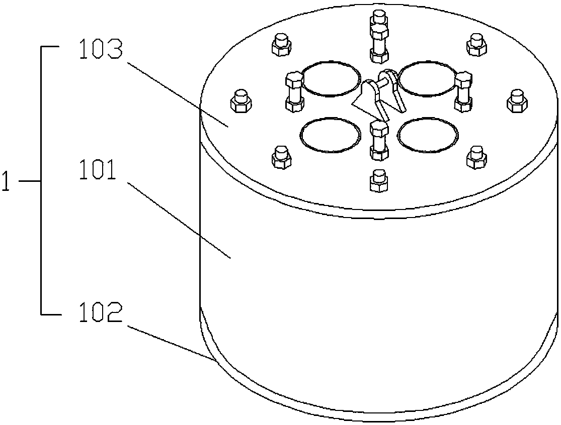
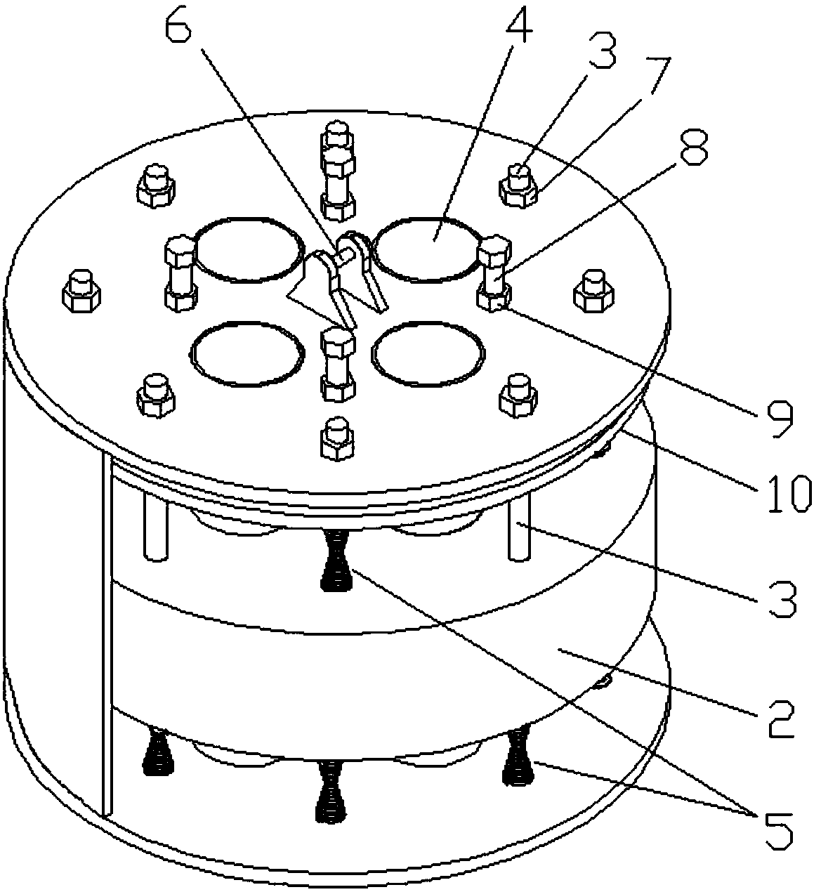
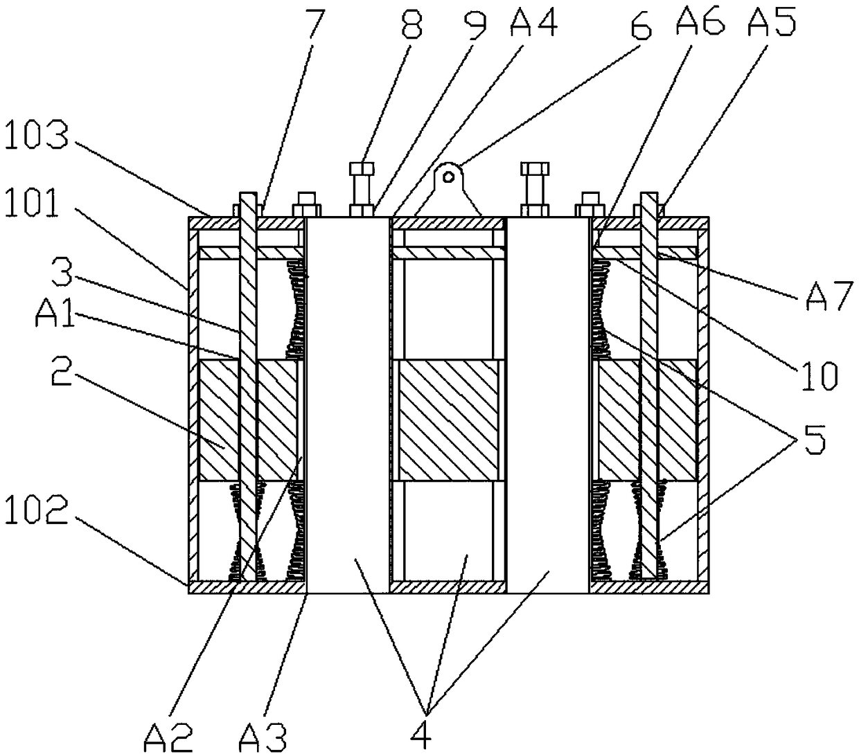
[0016] The structure of this embodiment includes a housing 1, a central vibrator 2, a guide rod 3, an exhaust cylinder 4, and a spring 5. The inside of the housing 1 is a cylindrical cavity, and the central vibrator 2 is arranged in the housing 1. The central vibrator 2 is provided with a plurality of first through holes A1, and a plurality of guide rods 3 respectively pass through the first through holes A1, and the upper and lower ends are respectively connected to the top and bottom of the housing 1, and the guide rods below the central vibrator 2 Section 3 is covered with a spring 5, the central vibrator 2 is also provided with a plurality of second through holes A2, the bottom of the housing 1 is provided with a third through hole corresponding to the second through hole A2, and the top of the housing 1 There is a fourth through hole corresponding...


PUM


Abstract

The invention provides a reciprocating type vibratory forced ramming hammer. After the hammer drops once, multi-time vibratory ramming on a pretreatment foundation can be realized, and damages of thefoundation structure are effectively prevented. The reciprocating type vibratory forced ramming hammer provided by the invention comprises a shell, a center vibrator, guide rods, exhaust cylinders andsprings; the inside of the shell is a cylindrical cavity; the center vibrator is arranged inside the shell and is provided with a plurality of first through holes; a plurality of guide rods penetratethrough the first through holes correspondingly; the upper and lower ends of the guide rods are connected with the top and the bottom of the shell correspondingly; guide rod sections below the centervibrator are correspondingly provided with the springs in a sleeving manner; the enter vibrator is also provided with a plurality of second through holes; the bottom of the shell is provided with third through holes corresponding to the second through holes; the top of the shell is provided with fourth through holes corresponding to the second through holes; each exhaust cylinder is of a hollow cylindrical structure of which the two ends are opened; the exhaust cylinders penetrates through the second through holes correspondingly; the two ends of the exhaust cylinders are connected with the third through holes and the fourth through holes correspondingly; and a hoisting hanger is arranged at the center of the outer side surface of the top of the shell.

Description

technical field [0001] The invention relates to the technical field of soft foundation treatment in the civil engineering industry, in particular to a reciprocating vibrating strong tamper. Background technique [0002] The dynamic compaction method is to use a large crawler-type dynamic compaction machine to freely drop an 8-30-ton heavy hammer from a height of 6-30 meters to compact the soil strongly, rapidly increase the bearing capacity and compression modulus of the foundation, and form a relatively uniform, The dense foundation changes the pore distribution of the foundation soil within a certain depth of the foundation. Dynamic compaction construction has been widely used in foundation reinforcement projects such as highways, railways, airports, nuclear power plants, large industrial areas, and port reclamation. [0003] Traditional dynamic ramming hammers are divided into filling hammers, combined hammers, and cast iron hammers. One lift can only achieve one tamping...

Claims


Application Information

Patent Timeline
Patent Type & Authority Applications(China)
IPC IPC(8): E02D3/046
CPCE02D3/046
Inventor 谷孝建
Owner WUHAN NANFANG XUYU TECH ENG CO LTD
Why Eureka
Try Eureka