A gas-assisted optional injector

An injector and air-assisted technology, which is applied in exhaust devices, machines/engines, noise reduction devices, etc., can solve the problems of reduced dosage, carbon black accumulation, blockage, etc., to prevent the formation of carbon black and high spray quality Effect

Active Publication Date: 2017-01-18
CHINA FAW LIMITED WUXI FUEL INJECTIONEQUIP RES INST +1
View PDF2 Cites 0 Cited by
  • Summary
  • Abstract
  • Description
  • Claims
  • Application Information

AI Technical Summary

Problems solved by technology

For dosing fuel into the exhaust gas flow, conventional multi-hole and single-hole injection valves can be used, but they have the disadvantage that the holes become clogged due to soot deposits in the exhaust gas, as a consequence of which the dosing will vary with the work The time continues to decrease, and there may even be a phenomenon that the dosing operation cannot be performed
This patented technology also has the deficiencies in the following aspects: 1. When the pressurized air and the pressurized fluid converge, because the number of air nozzles and fluid nozzles arranged in the circumferential direction is limited by their size, the spray oil beam can only be a few scattered oil beams
2. Since the nozzle hole at the head of the HC injector is normally open, and the structure such as an inverted cone is not used for sealing, when the injector does not work for a long time, a large amount of carbon black will accumulate in the nozzle hole of the head and cause blockage
3. Pressurized air and pressurized fluid cannot be switched. When the pressurized air pressure is small or lacking, the effect of mutual collision will not be produced.

Method used


Image

  • A gas-assisted optional injector
  • A gas-assisted optional injector
  • A gas-assisted optional injector

Examples


Embodiment Construction

[0028] The present invention will be further described in detail below in conjunction with the accompanying drawings and specific preferred embodiments.

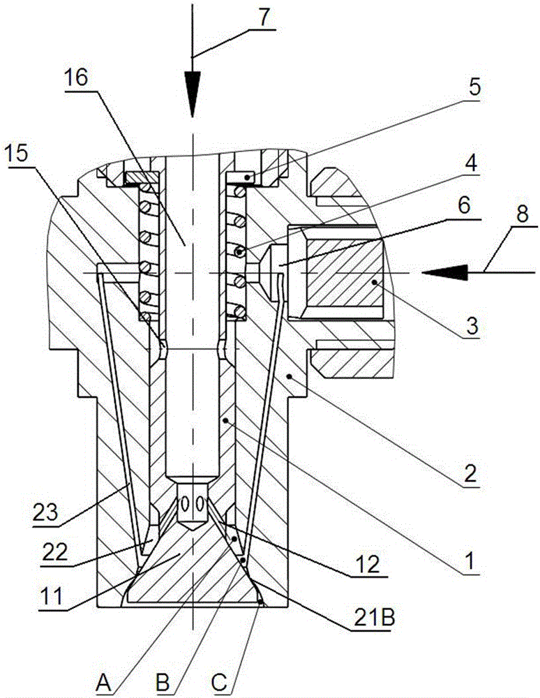
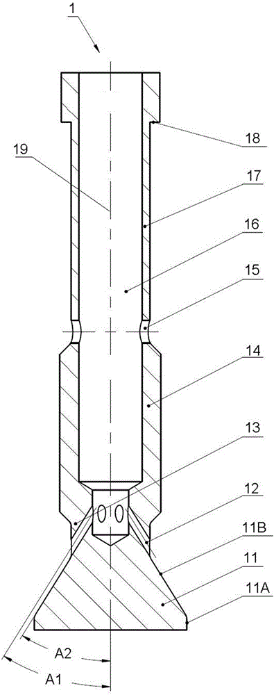
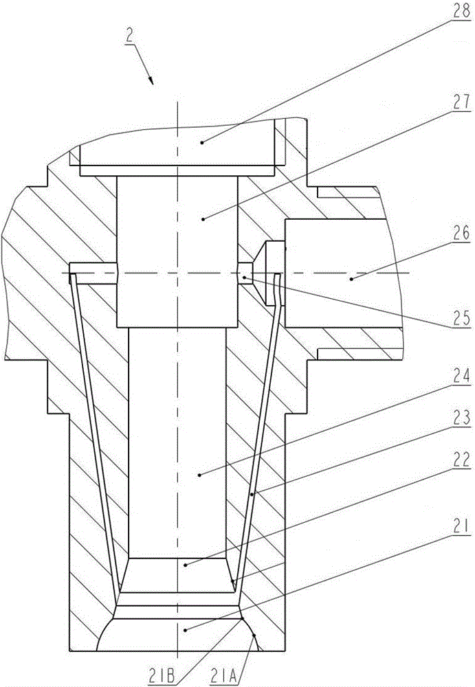
[0029] Such as figure 1 and Figure 5 As shown, a gas-assisted optional injector includes a valve core 1 and a valve seat 2 that can cooperate with each other and are arranged coaxially. The valve core 1 is preferably able to move axially in the valve seat 2. Of course, as in the CN 102182533 A patent, the injector can be set to a normally open state, and the valve core 1 remains stationary relative to the valve seat 2, which also belongs to the present invention scope of protection.

[0030] The mechanism for driving the valve core 1 to move axially relative to the valve seat 2 is a relatively mature prior art, such as using electromagnet on-off or spring force to automatically reset and the like.

[0031] The automatic reset by spring force is used as a specific embodiment below to describe the present invention in more...


PUM


Abstract

The invention discloses an air-assisted selectablejet. The air-assisted selectablejet comprises a valve core and a valve seat, wherein a plurality of jet holes are formed in the circumferential direction of the valve core; the valve core can axially move and is provided with a conical head; an inverted cone cavity which is through in the full-circumferential direction is formed in the valve seat; the inverted cone cavity, an air inlet in the top of the valve seat and a hollow accommodating cavity of the valve core are communicated with one another; the bottom of the inverted cone cavity and each jet hole are gathered at a cavity outlet. By adopting the structure, an atomizing oil beam flowing through the cavity outlet can be in a double-umbrella atomizing state in the full-circumferential direction, so that the atomizing quality is high, and forming of carbon black can be effectively prevented. In addition, due to the communication of the inverted cone cavity, the air inlet and the hollow accommodating cavity, mutual switching operation between air and fluid can be realized by controlling pressure difference between pressurized fluid and pressurized air. Furthermore, the conical head of the valve core can be sealed with the valve seat, so that the carbon black cannot enter the jet, external coke can be tangentially scoured, and the valve core can beopened relatively favorably.

Description

technical field [0001] The invention relates to an exhaust gas aftertreatment system, such as a fluid injector used in a DPF system, in particular to a gas-assisted optional injector. Background technique [0002] With the continuous improvement of emission regulations on engine exhaust emission limits, for example, DPF exhaust after-treatment systems are widely used in vehicles to remove particulate matter in exhaust streams. With the accumulation of particulate matter, a device is needed, such as the injector disclosed in the present invention, to inject fuel to support combustion and regenerate the DPF. For dosing fuel into the exhaust gas flow, conventional multi-hole and single-hole injection valves can be used, but they have the disadvantage that the holes become clogged due to soot deposits in the exhaust gas, as a consequence of which the dosing will vary with the work The time continues to decrease, and even the dispensing operation may not be possible. [0003] F...

Claims


Application Information

Patent Timeline
Patent Type & Authority Patents(China)
IPC IPC(8): F01N3/025
Inventor 陈希颖王健张庆刘志华宋睿智王政杨晓锋张珂白冲孙立旺
Owner CHINA FAW LIMITED WUXI FUEL INJECTIONEQUIP RES INST
Why Eureka
Try Eureka