
Magnet gripping device

A grasping device and magnet technology, applied in the field of magnets, can solve the problems of not meeting production requirements, affecting the assembly speed of finished products, low efficiency, etc. Effect

Pending Publication Date: 2018-06-12
东莞龙昌数码科技有限公司
View PDF0 Cites 1 Cited by
  • Summary
  • Abstract
  • Description
  • Claims
  • Application Information

AI Technical Summary

Problems solved by technology

[0002] Magnets are very common in daily life. They are often used in various products such as relays, speakers, motors, and assembled toys. The assembly speed of the finished product is directly related to the manufacturing cost. The difficulties encountered in the grasping of the existing magnets are mainly as follows: First, because the magnet has magnetic properties, it will be difficult to grasp the magnet with metal claws. Separation cannot better achieve a single magnet delivery; second, the composition of the magnet is iron, cobalt, nickel and other atoms, which are soft and easy to be crushed and damaged when subjected to a large force; Or 2, the quantity is small, the speed is slow, the efficiency is low, and the production requirements cannot be met

Method used


Image

  • Magnet gripping device
  • Magnet gripping device
  • Magnet gripping device

Examples


Embodiment Construction

[0016] Below in conjunction with accompanying drawing, the specific embodiment of the present invention is described further:

[0017] In the description of the present invention, it should be noted that the terms "center", "upper", "lower", "left", "right", "vertical", "horizontal", "inner", "outer" etc. The indicated orientation or positional relationship is based on the orientation or positional relationship shown in the drawings, and is only for the convenience of describing the present invention and simplifying the description, rather than indicating or implying that the indicated position or element must have a specific orientation, and must have a specific orientation. construction and operation, therefore, should not be construed as limiting the invention.

[0018] In the description of the present invention, it should be noted that unless otherwise specified and limited, the terms "installation", "connection" and "connection" should be understood in a broad sense, for...


PUM


Abstract

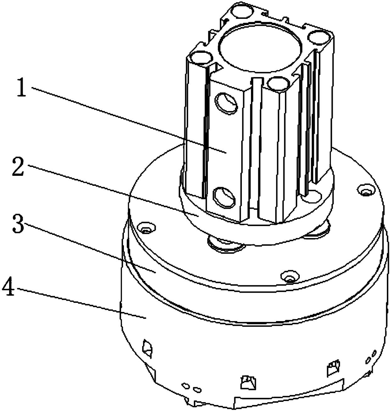
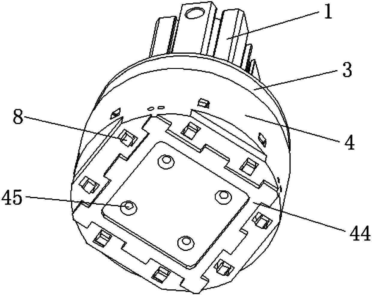
The invention relates to a magnet gripping device which comprises an air cylinder, an air cylinder mounting plate and a movable seat, wherein the air cylinder is mounted above the air cylinder mounting plate; an air cylinder piston rod penetrates through the air cylinder mounting plate downwards to be connected with the movable seat; the lower part of the movable seat is mounted in the cavity of agripping seat in a sleeving manner; a plurality of guide rods vertically downwards and a plurality of female wedge blocks are mounted at the bottom of the movable seat; the gripping seat is providedwith a guide hole, a wedge block mounting groove and a gripper mounting groove; sub wedge blocks are horizontally mounted in the wedge block mounting groove; a gripper is rotatably mounted in the gripper mounting groove through a pivot; the air cylinder drives the movable seat to move downwards; the movable seat moves downwards under the precise guiding function of the guide rods and the guide hole; the female wedge blocks move downwards to drive the sub wedge blocks to move outwards through inclination plane movement; the sub wedge blocks drive the gripper to rotate and shrink through a spring; the gripper and a limiting boss jointly clamp and grip magnets; the gripper elastically grips the magnets to prevent the magnets from rigid stressed damage; and in addition, the number of the gripper is increased according to the actual demand, so that the number of the magnets gripped at one time is large to meet the production demand.

Description

technical field [0001] The invention relates to the field of magnets, in particular to a magnet grasping device. Background technique [0002] Magnets are very common in daily life. They are often used in various products such as relays, speakers, motors, and assembled toys. The assembly speed of the finished product is directly related to the manufacturing cost. The difficulties encountered in the grasping of the existing magnets are mainly as follows: First, because the magnet has magnetic properties, it will be difficult to grasp the magnet with metal claws. Separation cannot better achieve a single magnet delivery; second, the composition of the magnet is iron, cobalt, nickel and other atoms, which are soft and easy to be crushed and damaged when subjected to a large force; Or 2, the quantity is small, the speed is slow, the efficiency is low, and the production requirements cannot be met. Contents of the invention [0003] In view of the technical problems in the pr...

Claims


Application Information

Patent Timeline
IPC IPC(8): B23P19/00
CPCB23P19/00B23P19/007
Inventor 梁钟铭蔡鹤皋洪炳镕
Owner 东莞龙昌数码科技有限公司
Learn More