
Material mixing device

A mixing device and mixing technology, applied in mixers, transportation, packaging, dissolution, etc., can solve problems such as inability to automatically feed materials

Active Publication Date: 2018-06-12
广东粤丰建材有限公司
View PDF4 Cites 11 Cited by
  • Summary
  • Abstract
  • Description
  • Claims
  • Application Information

AI Technical Summary

Problems solved by technology

[0004] The present invention intends to provide a mixing device to solve the problem that the existing mixing device cannot automatically feed materials

Method used


Image

  • Material mixing device
  • Material mixing device

Examples


Embodiment Construction

[0022] The following is further described in detail through specific implementation methods:

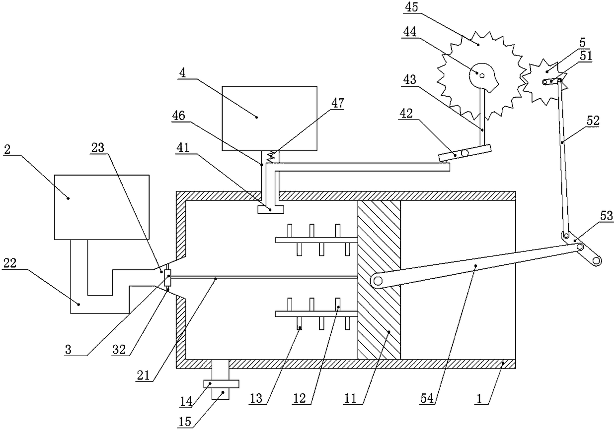
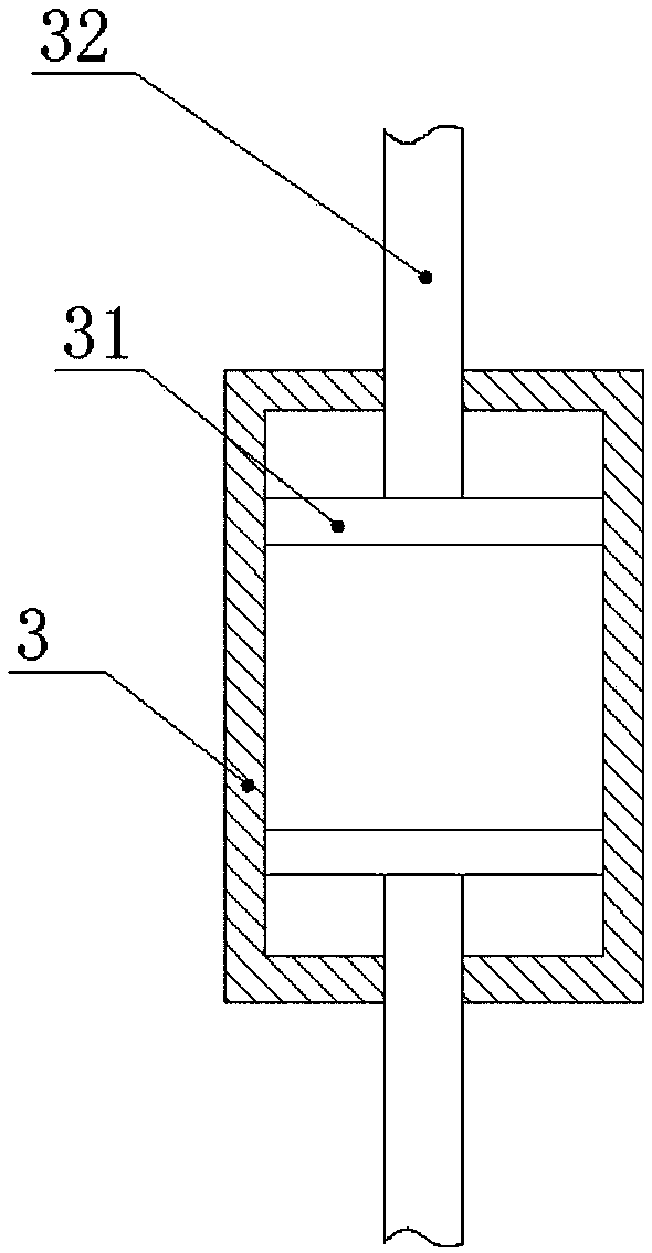
[0023] The reference signs in the drawings of the description include: mixing box 1, first piston 11, first mixing blade 12, second mixing blade 13, valve 14, discharge pipe 15, first charging box 2, telescopic Rod 21, U-shaped pipe 22, first feed pipe 23, second piston 3, slide bar 31, pole 32, second charging box 4, T-shaped bar 41, lever 42, ejector rod 43, cam 44, Large gear 45, second feed pipe 46, spring 47, pinion 5, crank 51, connecting rod 52, swing bar 53, pull bar 54.

[0024] Such as figure 1 As shown, a mixing device of the present invention includes a mixing box 1 arranged horizontally, a first piston 11 is slidably arranged in the mixing box 1, a first charging box 2 is arranged on the left side of the mixing box 1, and a first charging box 2 is arranged on the left side of the mixing box 1. The bottom of the charging box 2 is connected with a U-shaped pipe 22, and t...


PUM


Abstract

The invention relates to the technical field of stirring equipment and specifically relates to a material mixing device which comprises a material mixing box, wherein the material mixing box is horizontally arranged, a first piston is arranged in the material mixing box in a sliding mode, a second feeding box is arranged above the material mixing box, a lever is arranged on one side of the secondfeeding box, a gear set is arranged above the lever, a large gear in the gear set is coaxially provided with a cam, one end of the lever is connected with an ejector rod, the other end of the ejectorrod abuts against the cam, a second feeding pipe is communicated between the second feeding box and the material mixing box, a T-shaped rod is arranged in the second feeding pipe in a sliding mode, ahorizontal straight part of the T-shaped rod is arranged in the material mixing box, a vertical straight part of the T-shaped rod extends out of the second feeding pipe and is connected with the otherend of the lever, a small gear in the gear set is coaxially connected with a crank, a connection rod is hinged to the other end of the crank, a swinging rod is arranged under the connection rod in arotating mode, the free end of the swinging rod is in hinge connection with the connection rod, a pull rod is hinged to the swinging rod, and the other end of the pull rod is in hinge connection withthe first piston. The material mixing device disclosed by the invention solves the problem that an existing material mixing device cannot feed materials automatically.

Description

technical field [0001] The invention relates to the technical field of stirring equipment, in particular to a mixing device. Background technique [0002] In life, we often encounter situations that require different materials to be mixed and stirred together, such as the mixing of building materials, the mixing of medicines, and kitchen cooking. The traditional method is to manually mix different materials together, which not only requires a lot of manpower, but also has low production efficiency. [0003] A type of material mixing device has appeared in the prior art. This type of mixing device includes a stirring tank and a stirring shaft arranged in the stirring tank, and a driving mechanism is used to drive the stirring shaft to rotate to realize mixing of materials in the stirring tank. Although this type of stirring device can realize automatic mixing of materials, this type of mixing device cannot realize automatic feeding of materials. When realizing large-scale mi...

Claims


Application Information

Patent Timeline
Patent Type & Authority Applications(China)
IPC IPC(8): B01F13/02B01F15/02B01F33/40
CPCB01F33/4094B01F35/717
Inventor 李龙德
Owner 广东粤丰建材有限公司
Learn More