
A kind of i3c bus control interface circuit

A technology of interface circuit and bus control, applied in the direction of logic circuit, logic circuit interface device, logic circuit connection/interface layout, etc., to achieve the effect of solving the increase of power consumption, reducing power consumption and improving equipment performance

Active Publication Date: 2019-03-08
山东高云半导体科技有限公司
View PDF11 Cites 0 Cited by
  • Summary
  • Abstract
  • Description
  • Claims
  • Application Information

AI Technical Summary

Problems solved by technology

[0005] The purpose of the present invention is to provide a kind of I3C bus control interface circuit, aiming at solving the problem existing in the prior art that the power consumption of the pull-up resistor cannot be reduced on the basis of ensuring the existing performance of the I3C circuit

Method used


Image

  • A kind of i3c bus control interface circuit
  • A kind of i3c bus control interface circuit
  • A kind of i3c bus control interface circuit

Examples


Embodiment Construction

[0037] In order to make the objectives, technical solutions and advantages of the present invention clearer, the present invention will be further described in detail below with reference to the accompanying drawings and embodiments. It should be understood that the specific embodiments described herein are only used to explain the present invention, but not to limit the present invention.

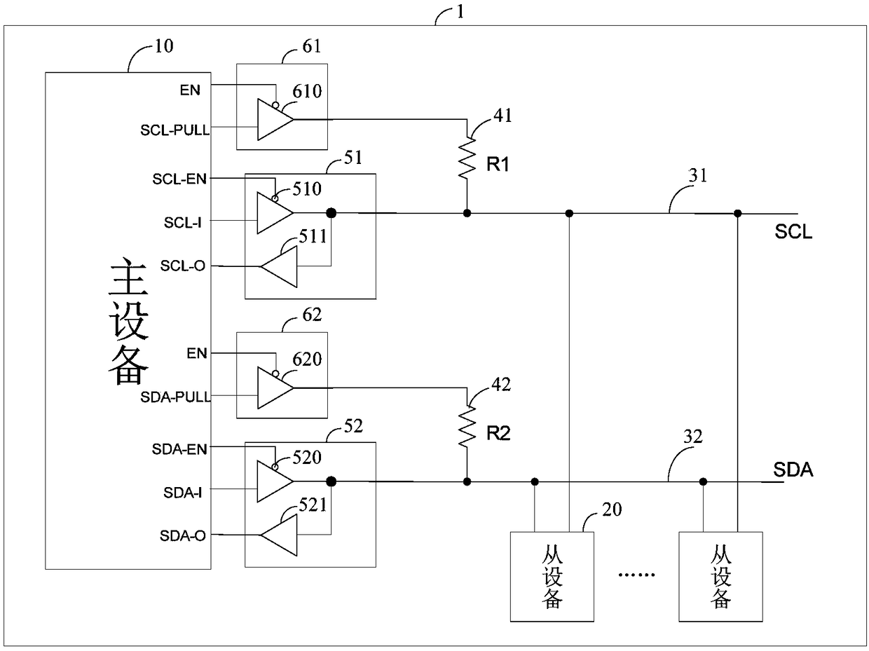
[0038] Please refer to the following Figure 1 to Figure 5 The implementation of the present invention is described in detail:

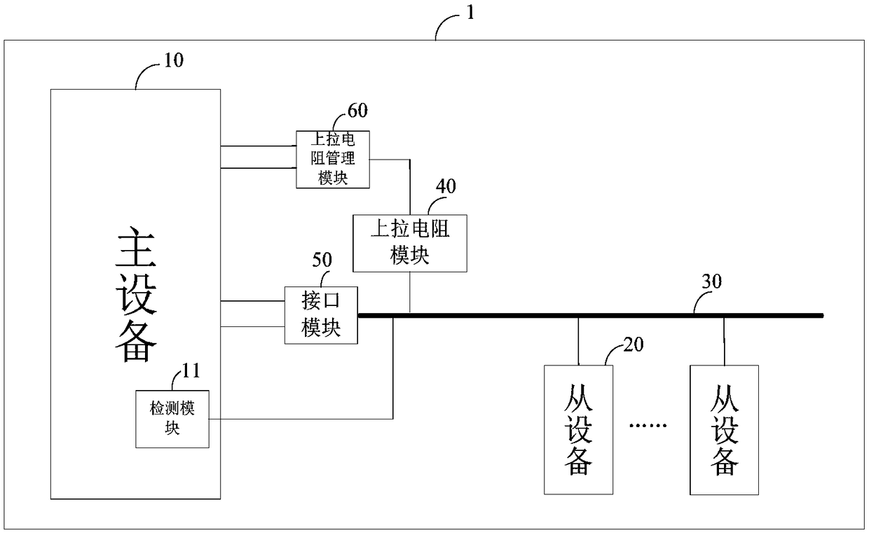
[0039] figure 1 A schematic diagram of the circuit structure of the I3C bus control interface circuit provided by an embodiment of the present invention is shown. For the convenience of description, only the parts related to this embodiment are shown, and the details are as follows:

[0040] like figure 1 As shown, an I3C bus control interface circuit provided by an embodiment of the present invention includes a master device 10, at least one slave device 20, an...


PUM


Abstract

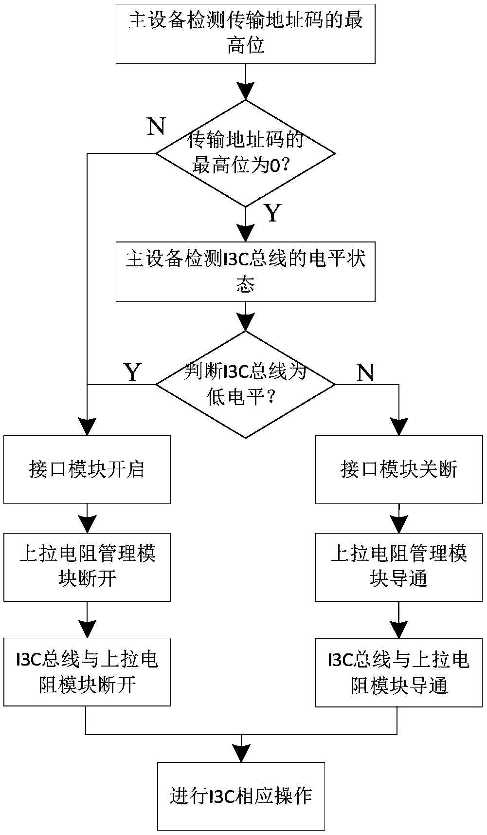
The invention relates to the technical field of I3C integrated circuits, and provides an I3C bus control interface circuit, which comprises a master device, a slave device, an I3C bus, an interface module, a pull-up resistor management module and a pull-up resistor module. When the I3C bus carries out address operation, the master device detects a transmission address code of the I3C bus; when themaster device detects that the transmission address code of the I3C bus meets a preset rule, the master device detects a level state of the I3C, controls connection or disconnection of the interfacemodule and the I3C bus through configuration of a switch mode of the interface module according to the level state, and conducts or breaks the connection between the I3C bus and the pull-up resistor module by controlling a switch state of the pull-up resistor management module according to the transmission address code and the level state, so that the purposes of dynamically controlling the connection or disconnection between the I3C bus and the pull-up resistor module and dynamically adjusting the connection state of a pull-up resistor of the I3C bus in order to reduce the power consumption of the pull-up resistor and the power consumption of the I3C bus circuit.

Description

technical field [0001] The invention relates to the technical field of I3C integrated circuits, in particular to an I3C bus control interface circuit. Background technique [0002] The full name of IP core is Intellectual Property Core (Intellectual Property Core), which refers to the chip design module provided by a party. Designers can use the IP core as the basis for logic design of application-specific integrated circuits or field programmable logic gate arrays (FPGA) to shorten the Design cycle, improve design quality and efficiency. [0003] With the rapid development of mobile devices, the drawbacks of sensor devices such as I2C (Inter-Integrated Circuit) and SPI (SerialPeripheral Interface) have gradually emerged. Subsequently, the MIPI Alliance proposed the I3C standard specification, which absorbed, combined and improved I2C, Interface solutions such as SPI and UART (Universal Asynchronous Receiver / Transmitter) provide the necessary convenience and system-level ad...

Claims


Application Information

Patent Timeline
Patent Type & Authority Patents(China)
IPC IPC(8): H03K19/0175H03K19/00
CPCH03K19/0008H03K19/017509
Inventor 杜金凤任程程孙莉莉赵井坤
Owner 山东高云半导体科技有限公司
Learn More