
An automatic control system for cognitive radio equipment

An automatic control system and cognitive radio technology, applied in the field of control systems, can solve the problems of the power failure of the backup power supply, the rapid decline of the battery life, the ineffectiveness of the wireless communication equipment, etc. Effect

Active Publication Date: 2019-12-31
北京响之壹科技有限公司
View PDF6 Cites 0 Cited by
  • Summary
  • Abstract
  • Description
  • Claims
  • Application Information

AI Technical Summary

Problems solved by technology

[0003] During the operation of cognitive radio equipment, the power provided to the equipment is particularly important. Whether the power output is stable or not is directly related to the operating status of cognitive radio equipment. Therefore, the automatic control system also includes power control. Now Some cognitive radio devices are generally used as a small base station, so if there is a power outage, the cognitive radio device will not work, which will easily cause wireless communication devices in an area to be unable to effectively carry out wireless communication. Therefore, it is very necessary to provide timely power supply for cognitive radio equipment during power failure. In the prior art, a battery is generally used as a backup power supply, and then when a power failure occurs, a switch is used to switch the backup power supply The power switch is connected to the cognitive radio device to avoid the problem that the cognitive radio device cannot work due to a power outage. However, it needs to be switched back after the power is turned on again. If it is directly switched back, the battery will not be able to work. Charging, but there will be a problem that the backup power supply is out of power later. If the battery is fully charged first and then switched back, then there will be a problem that the battery is charged too frequently and the battery life is reduced too quickly.

Method used


Image

  • An automatic control system for cognitive radio equipment
  • An automatic control system for cognitive radio equipment

Examples


Embodiment approach

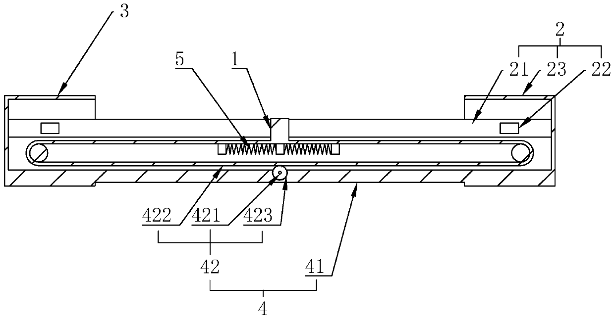
[0020] As an improved specific implementation, the drive mechanism 42 includes a rotating motor 421, a toothed belt 422, and a motor controller that drives the rotating motor 421 forward and reverse. The motor controller is coupled to the power-off detection circuit and two The voltage sampling circuit is coupled, the body of the rotating motor 421 is fixedly connected to the lower side of the middle part of the transfer guide rail 41, and the transfer gear 423 is sleeved on the rotating shaft, and the two ends of the transfer guide rail 41 are rotatably connected with fixed pulley, the two ends of the toothed belt 422 are fixedly connected to the left and right sides of the battery 1 after bypassing the fixed pulleys at the two ends of the transfer guide rail 41, and the transfer gear 423 is meshed with the toothed belt 422, and the toothed belt 422 is used to rotate The setting of the motor 421 and the transfer gear 423 can effectively use the forward rotation and reverse rot...

specific Embodiment approach

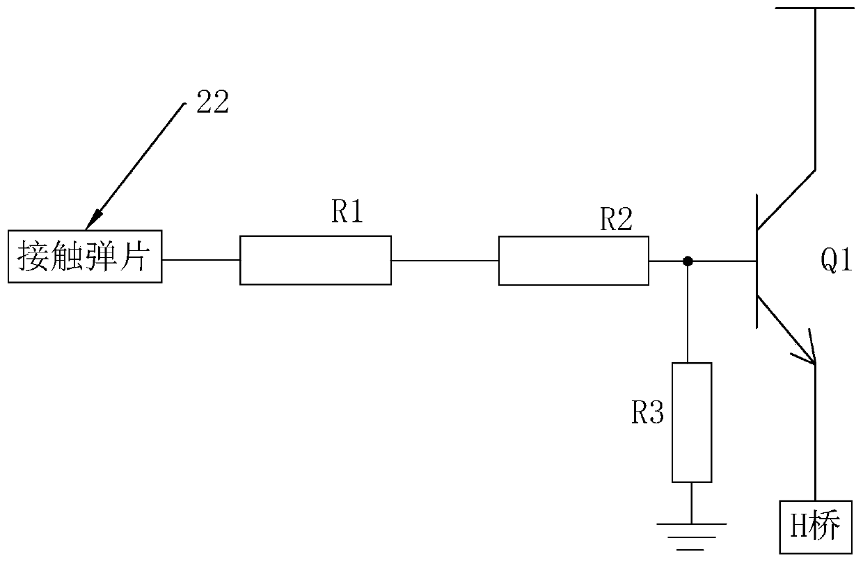
[0021] As an improved specific implementation, the voltage sampling circuit in the power connection device 2 includes:

[0022] The switch tube Q1, the first end of the switch tube Q1 is coupled to the power supply, the second end is coupled to the motor controller, the control end is coupled to a resistor R1 and a resistor R2 connected in series, and then coupled to the contact shrapnel 22. The resistance R3 is connected to the ground, and through the setting of the switching tube Q1, the breaking voltage of the switching tube Q1 can be used as the low-voltage threshold, so the overall structure is simple, and the volume is small, which can be better suitable for cognitive radio equipment. The switch tube Q1 in this embodiment is a PMOS tube, which is turned on only when the voltage is lower than a certain value.

[0023] As an improved specific implementation, the motor controller includes:

[0024] H bridge, the H bridge has a forward rotation input interface, a reverse in...


PUM


Abstract

The invention discloses an automatic control system for cognitive radio equipment. The automatic control system comprises a power supply used for providing the cognitive radio equipment with electricity, wherein the power supply comprises a storage battery, a switchgear, a charge device and a switching device; the switching device is used for driving the storage battery to move on the switchgear and the charge device back and forth; the switchgear is electrically connected with the external cognitive radio equipment; the charge device is electrically connected with an external power supply andthe switchgear; and a vacant position is arranged between the charge device and the switchgear. According to the automatic control system for the cognitive radio equipment, vacancy when the storage battery is not used can be achieved through the arrangement of the vacant position, and the problem that the service life of the storage battery is shortened due to too many charge cycles of the storage battery is solved.

Description

technical field [0001] The present invention relates to a control system, more specifically to an automatic control system for cognitive radio equipment. Background technique [0002] Cognitive radio equipment is the basic unit of cognitive radio communication. Whether its working status is normal or not directly affects the communication quality and status of cognitive radio. If it is viewed in the process of wireless communication, cognitive radio equipment will malfunction. , then it will lead to problems in wireless communication and cause huge communication losses. Therefore, in order to maintain the stability of cognitive radio equipment in the prior art, an automatic control system is generally set up to drive cognitive radio equipment, so that cognitive radio equipment The equipment can run more stably and reliably. [0003] During the operation of cognitive radio equipment, the power provided to the equipment is particularly important. Whether the power output is s...

Claims


Application Information

Patent Timeline
Patent Type & Authority Patents(China)
IPC IPC(8): H02J9/06H02J7/00
CPCH02J7/0045H02J9/06
Inventor 毛华庆李华伟叶舟
Owner 北京响之壹科技有限公司
Learn More