Gear transmission structure and mechanical dispenser
A technology of gear transmission and external gear, applied in the direction of gear transmission device, manipulator, transmission device, etc., can solve the problems of rising cylinder maintenance rate, reducing production efficiency, easy wear of cylinder push rod, etc., to achieve convenient use and simple structure. Effect
- Summary
- Abstract
- Description
- Claims
- Application Information
AI Technical Summary
Problems solved by technology
Method used
Image

Examples
Embodiment 1
[0043] The specific implementation of this embodiment is as follows:
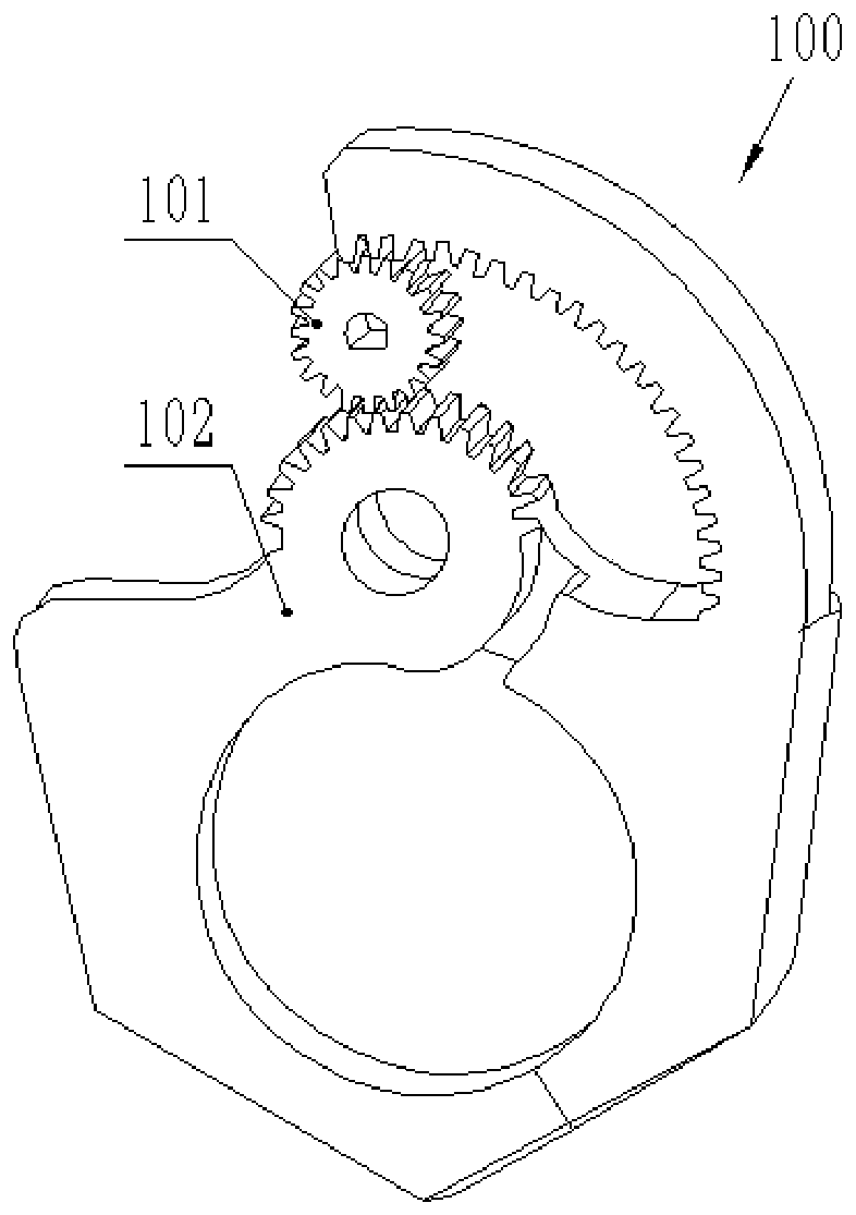
[0044] like figure 1 As shown in -2, this embodiment provides a gear transmission structure 100, including a driving gear 101 and a driven gear 102, the driving gear 101 rotates under the action of an external force, and the driving gear 101 drives the driven gear 102 to rotate; the driven gear 102 is provided with Two sets of tooth structures are arranged opposite to each other, and the driving gear 101 is arranged in the middle of the two sets of tooth structures, and is meshingly connected with the two sets of tooth structures respectively.
[0045] It should be noted that the structure of the driven gear 102 in this embodiment is relatively novel, and it is two sets of tooth structures oppositely arranged. There is a path for the driving gear 101 to rotate, and paths of different sizes can be set according to actual rotation needs; during actual rotation, the driving gear 101 rotates preferentially, and ...
Embodiment 2
[0048] like figure 1 -2, the gear transmission structure 100 provided in this embodiment includes all the technical features of the first embodiment above, and also includes the following features:
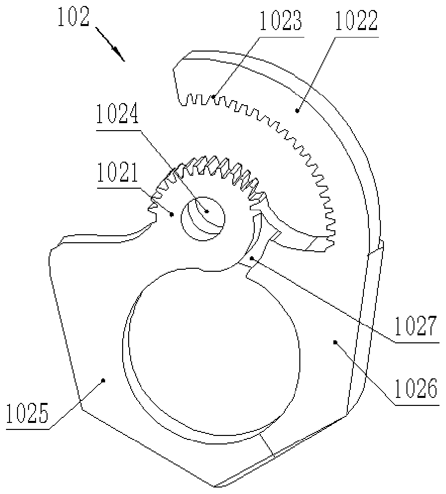
[0049] An optional technical solution of this embodiment is that the driven gear 102 includes a rotating external gear 1021 and a rotating internal gear 1022 , and the rotating internal gear 1022 is arranged coaxially with the rotating external gear 1021 .
[0050] The optional technical solution of this embodiment is that the rotating external gear 1021 is provided with a first grasping part 1025, and the rotating internal gear 1022 is provided with a second grasping part 1026; Rotate to rotate; the second grasping part 1026 rotates with the rotation of the rotating inner gear 1022 .
[0051] It should be noted that the gear transmission structure 100 of this embodiment is mainly driven by the joint action of the rotating external gear 1021, rotating internal gear 1022 and drivi...
Embodiment 3
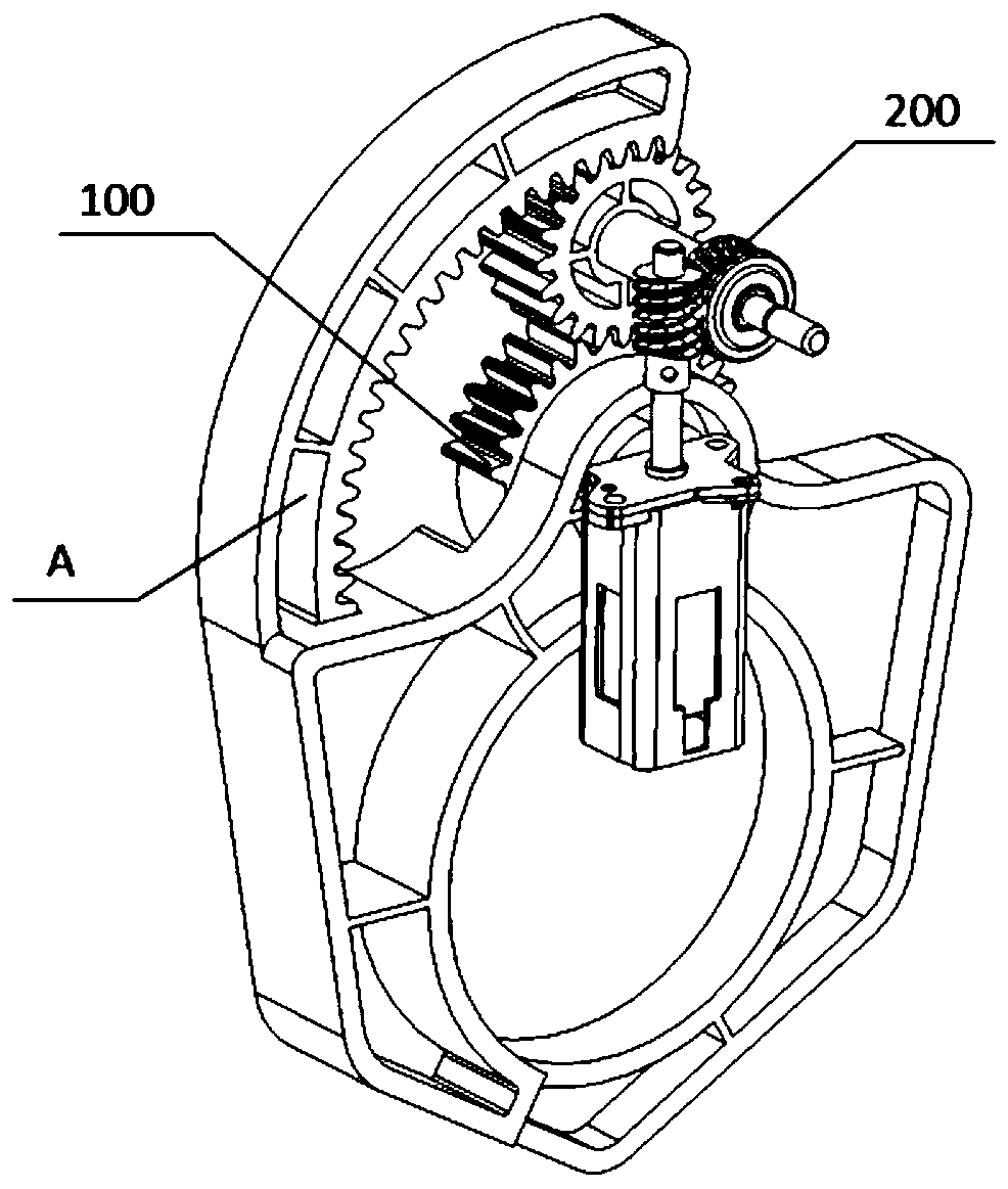
[0068] like figure 1 As shown in -5, this embodiment provides a mechanical dispenser, including a power output assembly 200 and the gear transmission structure of the second embodiment above, the power output assembly 200 includes a drive motor 201, a worm wheel 203, a worm 202 and an output shaft 204, One end of the output shaft 204 is coaxially connected with the driving gear 101, the other end of the output shaft 204 is coaxially connected with the worm wheel 203, the driving motor 201 is connected with the worm 202, and the worm 202 is engaged with the teeth of the worm wheel 203; the driving motor 201 rotates through the driving worm 202, Drive the worm wheel 203 to rotate, and the worm wheel 203 rotates to drive the output shaft 204 to rotate; the output shaft 204 drives the driving gear 101 to rotate, and then realizes driving the above-mentioned gear transmission structure 100 to carry out the common grasping of the first grasping part 1025 and the second grasping part ...
PUM
 Abstract
Description
Claims
Application Information
 - Generate Ideas
- Intellectual Property
- Life Sciences
- Materials
- Tech Scout
- Unparalleled Data Quality
- Higher Quality Content
- 60% Fewer Hallucinations
Browse by: Latest US Patents, China's latest patents, Technical Efficacy Thesaurus, Application Domain, Technology Topic, Popular Technical Reports.
© 2025 PatSnap. All rights reserved.Legal|Privacy policy|Modern Slavery Act Transparency Statement|Sitemap|About US| Contact US: help@patsnap.com