
Grinding-head upper mechanism for ceramic polishing machine

A ceramic polishing machine and grinding head technology, which is applied to the parts of grinding machine tools, grinding/polishing equipment, grinding/polishing safety devices, etc., can solve the problems of unfavorable workpiece quality, large friction coefficient, and slow running speed, etc. It achieves the effects of convenient inspection and maintenance, small friction coefficient and high limit speed

Inactive Publication Date: 2018-06-08
佛山市嘉印机械设备有限公司
View PDF7 Cites 0 Cited by
  • Summary
  • Abstract
  • Description
  • Claims
  • Application Information

AI Technical Summary

Problems solved by technology

[0003] The existing grinding head and motor are usually driven by V-belts. The upper mechanism of the grinding head used for ceramic polishing machines will vibrate greatly during operation, and the operation is not stable, which is not conducive to the quality of the workpiece during grinding. control, and at the same time the running speed is slow, it is not suitable for high-speed grinding; in addition, the existing grinding head is usually connected by a tapered roller bearing between the rotating shaft and the bearing seat, although it can bear a large axial load, However, the friction coefficient is large and the limit speed is low

Method used


Image

  • Grinding-head upper mechanism for ceramic polishing machine
  • Grinding-head upper mechanism for ceramic polishing machine
  • Grinding-head upper mechanism for ceramic polishing machine

Examples


Embodiment Construction

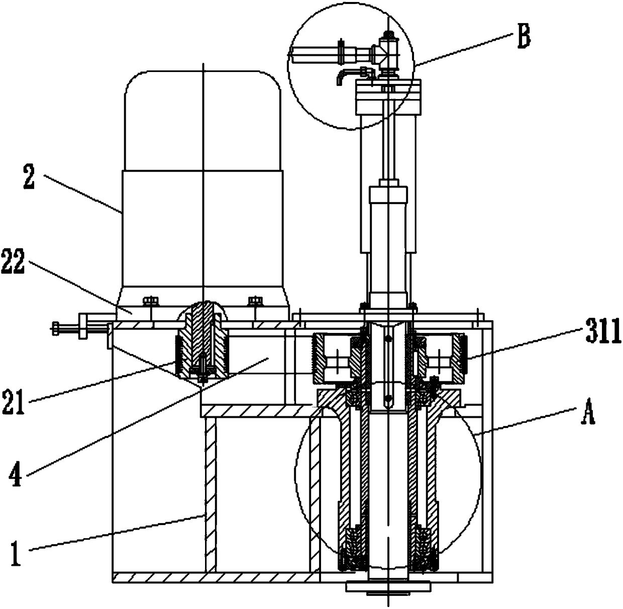
[0023] The present invention will be described in further detail below in conjunction with accompanying drawing, and these accompanying drawings are all simplified schematic diagrams, only illustrate the basic structure of the present invention in a schematic way, and the direction of this specific implementation is based on figure 1 Orientation is standard.

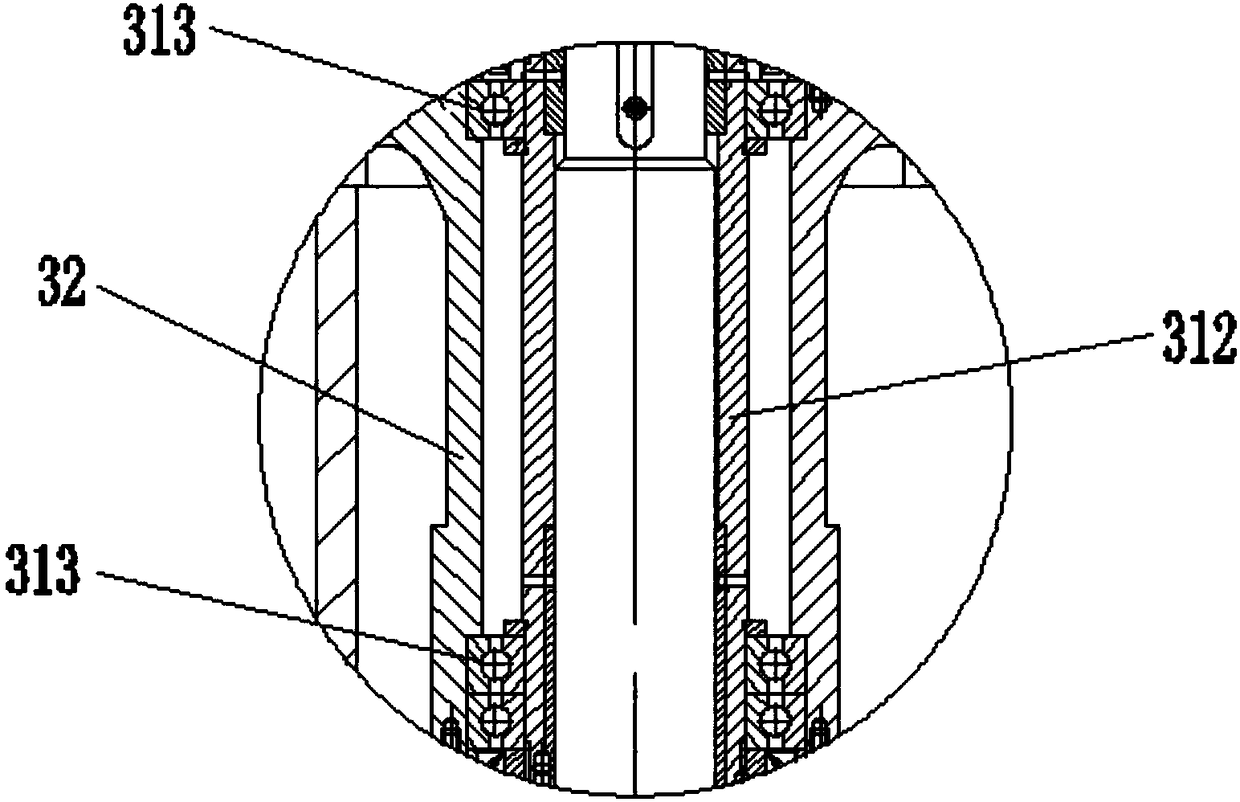
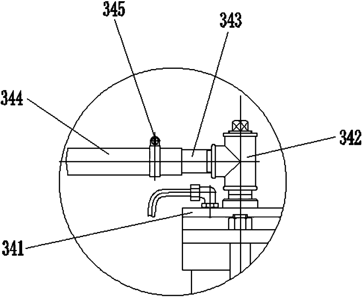
[0024] Such as Figure 1-Figure 6 As shown, the present invention is used for the upper mechanism of the grinding head of the ceramic polishing machine including frame 1, motor 2 and grinding head upper assembly 3, wherein:

[0025] Both the motor 2 and the grinding head upper assembly 3 are arranged on the frame 1, and a vibration-damping pad 22 is arranged between the motor 2 and the frame 1. The vibration-damping pad 22 includes a rubber vibration-damping plate 221 and is arranged in the rubber vibration-damping plate 221. The spring 222, the spring 222 is equally spaced and evenly distributed in the rubber damping p...


PUM


Abstract

The invention discloses a grinding-head upper mechanism for a ceramic polishing machine which is stable during running and high in rotation speed. The mechanism comprises a rack, a motor and a grinding-head upper assembly; a small V-ribbed belt wheel is arranged on a rotating shaft of the motor, and the grinding-head upper assembly comprises a main shaft, a bearing base, an air cylinder and a water inlet assembly; the main shaft is of a hollow structure, the middle of the main shaft is provided with a large V-ribbed belt wheel, the small V-ribbed belt wheel is in transmission connection with the large V-ribbed belt wheel through a V-ribbed belt, and a transmission sleeve is arranged below the large V-ribbed belt wheel; the bearing base sleeves the transmission sleeve, a first gap is formedbetween the inner surface of the bearing base and the outer surface of the transmission sleeve, and the two ends in the first gap are provided with deep groove ball bearings; a protection sleeve is arranged above the large V-ribbed belt wheel, a connection sleeve is arranged above the protection sleeve, a second gap is formed between the inner surface of the connection sleeve and the outer surface of the main shaft, and the middle and upper end of the second gap are provided with conical roller bearings; the top of the connection sleeve is provided with a pressing cover, the two ends of the pressing cover are fixedly connected with the air cylinder, and the air cylinder can drive the pressing cover to move up and down.

Description

technical field [0001] The invention relates to an upper mechanism of a grinding head for a ceramic polishing machine. Background technique [0002] The ceramic polishing machine is a precision polishing equipment. The material to be polished is placed on the polishing disc, the polishing disc rotates counterclockwise, the workpiece rotates, and the workpiece is pressed by gravity pressure, and the workpiece and the polishing disc are rubbed against each other to achieve polishing. Purpose, the grinding head mechanism of the ceramic polishing machine is an important part of the polishing machine, and the grinding head mechanism of the ceramic polishing machine is mainly composed of a grinding head, a motor and a transmission mechanism. [0003] The existing grinding head and motor are usually driven by V-belts. The upper mechanism of the grinding head used for ceramic polishing machines will vibrate greatly during operation, and the operation is not stable, which is not cond...

Claims


Application Information

Patent Timeline
Patent Type & Authority Applications(China)
IPC IPC(8): B24B41/04B24B55/00
CPCB24B41/04B24B55/00
Inventor 邹梓常
Owner 佛山市嘉印机械设备有限公司
Learn More