
Cut-in cut-out mechanism for infrared imaging load virtual focus lens

A technology of infrared imaging and virtual focus, applied in the direction of measuring devices, instruments, scientific instruments, etc., can solve inconvenient problems and achieve the effects of ensuring authenticity, ensuring pressure, improving exhaust efficiency and stabilizing effect

Inactive Publication Date: 2018-06-05
BEIJING AEROSPACE INST FOR METROLOGY & MEASUREMENT TECH +1
View PDF5 Cites 0 Cited by
  • Summary
  • Abstract
  • Description
  • Claims
  • Application Information

AI Technical Summary

Problems solved by technology

The use of black bodies to calibrate infrared imaging load equipment is mostly used in laboratories, which is relatively inconvenient

Method used


Image

  • Cut-in cut-out mechanism for infrared imaging load virtual focus lens
  • Cut-in cut-out mechanism for infrared imaging load virtual focus lens
  • Cut-in cut-out mechanism for infrared imaging load virtual focus lens

Examples


Embodiment Construction

[0015] The patent of the present invention will be described in detail below in conjunction with the accompanying drawings.

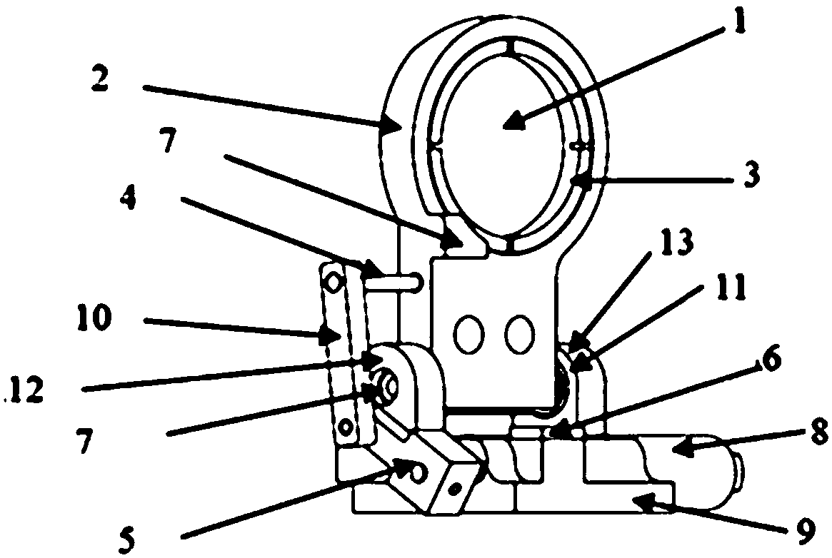
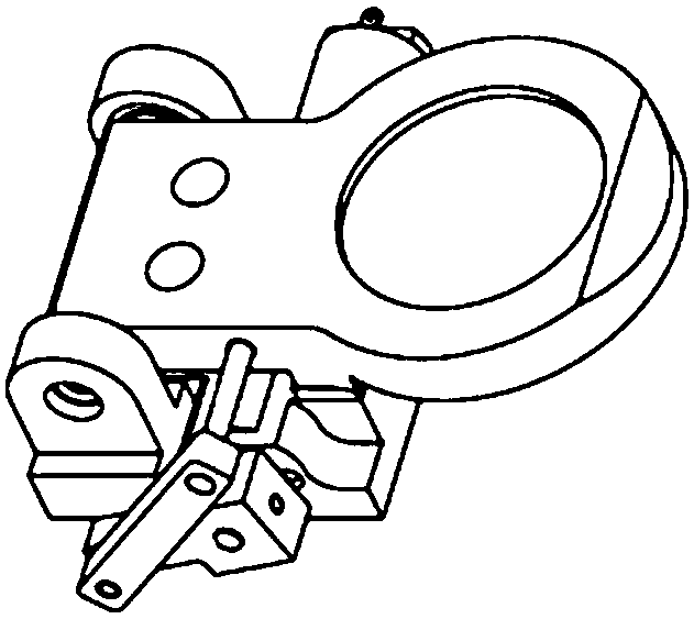
[0016] Such as figure 1 The cut-in and cut-out mechanism of the infrared imaging payload virtual focus lens shown includes a virtual focus lens 1 , a virtual focus lens seat 2 , a lens pressure ring 3 , a connecting rod A4 , a crank 5 , a motor 8 and a base 9 .

[0017] The motor 8 is fixed on the base 9 by screws, the crank 5 is installed on the output shaft of the motor 8, and the crank 5 and the 9 shafts of the motor are locked by jackscrews. The other end of the crank 5 is connected to the connecting rod B10, and the crank 5 and the connecting rod B10 can rotate relatively. One end of the connecting rod A4 is fixed on the virtual focus lens holder 2, and the other end is connected with the connecting rod B10, and can rotate relatively. Bearing A7 and bearing B11 are respectively installed on bearing housing A12 and bearing housing B13, bearing hou...


PUM


Abstract

An cut-in cut-out mechanism for an infrared imaging load virtual focus lens is composed of a virtual focal lens 1, a virtual focal lens holder 2, a lens pressing ring 3, a connecting rod A4, a crank 5, a motor 8 and a base 9. The motor 8 is fixed to the base 9 by screws. The crank 5 is mounted on the output shaft of the motor 8. The crank 5 and the motor 9 are locked by a jackscrew. The other endof the crank 5 is connected to a connecting rod B10. The crank 5 and the connecting rod B10 are relatively rotatable. One end of the connecting rod A4 is fixed to the virtual focal lens holder 2, andthe other end of the connecting rod A4 is connected with the connecting rod B10 and can rotate relative to the connecting rod B10. A bearing A7 and a bearing B11 are mounted on a bearing seat A12 anda bearing seat B13 respectively. The bearing seat A12 and the bearing seat B13 are mounted on the base 9 and fixed by screws. The lower side shaft of the virtual focal lens holder 2 is inserted into the bearing A7 and the bearing B11 such that the virtual focal lens holder 2 freely rotate around a rotation axis. The virtual focal lens 1 is installed on the inner side of the virtual focal lens holder 2 through the lens pressing ring 3. The optical axis direction of a imaging load system is the optical axis direction of the virtual lens 1 in the FIG 1.

Description

technical field [0001] The invention belongs to the field of cut-in and cut-out devices, and in particular relates to a cut-in and cut-out device suitable for virtual focus correction of infrared imaging loads. Background technique [0002] In recent years, infrared imaging technology has achieved more and more extensive development, and its core component, infrared focal plane array, plays a vital role in it. However, due to various reasons such as materials, manufacturing processes, spatial noise, and transient random noise, there will be certain inconsistencies between the response values ​​of each detection unit on the infrared focal plane to the same radiation surface source, which will eventually lead to the inconsistency of infrared imaging. In the case of poor image quality, etc., the above is the non-uniformity problem of the infrared detector. [0003] At present, the non-uniformity correction methods of infrared detectors include calibration correction methods an...

Claims


Application Information

Patent Timeline
Patent Type & Authority Applications(China)
IPC IPC(8): G01J5/00G01J5/08G01J5/02
CPCG01J5/00G01J5/0205G01J5/0806G01J2005/0077G01J5/80
Inventor 魏小林林森常虹刘晗何锁纯董斐付强张骢
Owner BEIJING AEROSPACE INST FOR METROLOGY & MEASUREMENT TECH
Learn More