Tubular shaft hinge

A hinge and tube shaft technology, applied in the field of mechanical parts, to achieve the effect of adding a single connection method

Pending Publication Date: 2018-06-05
GUANGDONG SHENLING ENVIRONMENT SYST CO LTD
View PDF5 Cites 1 Cited by
  • Summary
  • Abstract
  • Description
  • Claims
  • Application Information

AI Technical Summary

Problems solved by technology

[0004] In view of the deficiencies in the prior art above, the purpose of the present invention is to provide a heat pipe backplane system for cabinets, aiming to solve the problem that the backplane heat exchanger must be connected to the connecting pipe through a flexible pipe in the existing heat pipe backplane system technical problem

Method used


Image

  • Tubular shaft hinge

Examples


Embodiment Construction

[0014] The present invention provides a tube shaft hinge. In order to make the purpose, technical solution and effect of the present invention clearer and clearer, the present invention will be further described in detail below with reference to the accompanying drawings and examples. It should be understood that the specific embodiments described here are only used to explain the present invention, not to limit the present invention.

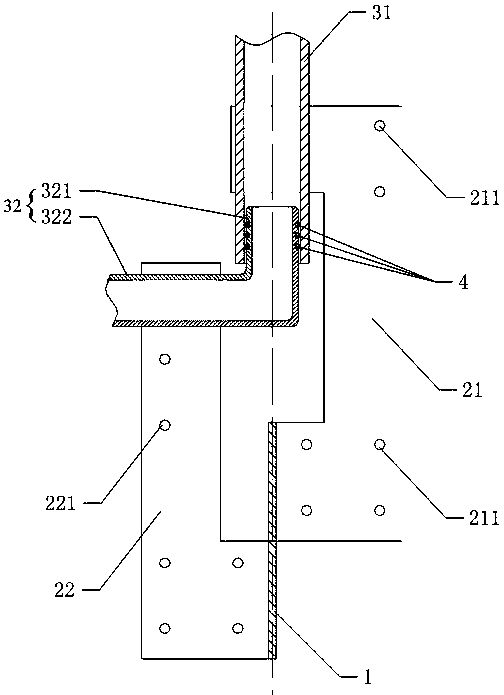
[0015] See first figure 1 , The invention provides a tubular shaft hinge.

[0016] The tube shaft hinge includes a pivot 1, two first leaf boards 21 and second leaf boards 22 that are rotatably connected to the pivot shafts, a first branch pipe 31 connected to the first leaf boards, and A second branch pipe 32 connected to the second leaf plate; the second straight pipe 32 includes an extended section 322 and a vertical section 321 connected to each other, and the vertical section 321 of the second branch pipe is inserted into the first branch...


PUM


Abstract

The invention discloses a tubular shaft hinge which comprises a pivot, a first hinge plate, a second hinge plate, a first branch tube and a second branch tube. The first hinge plate and the second hinge plate are rotatably connected with the pivot, the first branch tube is connected with the first hinge plate, the second branch tube is connected with the second hinge plate and comprises an extension section and a vertical section which are connected with each other, the vertical section of the second branch tube is inserted into the first branch tube and hermetically matched with the first branch tube, and the vertical section of the second branch tube, the first branch tube and the pivot of the hinge are coaxially arranged. The tubular shaft hinge thoroughly solves the technical problem that a flexible tube has to be used for connecting a back plate heat exchanger with a circulating tube in the prior art.

Description

technical field [0001] The invention relates to the technical field of mechanical parts, in particular to a tube shaft hinge. Background technique [0002] In the server cabinet heat pipe cooling system, the backplane heat exchanger is installed on the inner side of the cabinet door. In order to ensure the normal opening and closing of the cabinet door installed with the backplane heat exchanger, the inlet and outlet of each backplane heat The connection with the connecting pipe is not only complicated in construction but also extremely unsightly; and even if the flexible pipe is used to connect, the joints at both ends of the flexible section will easily become loose after the cabinet door is opened and closed many times, resulting in the leakage of working fluid. In addition, the connecting pipes in the prior art are welded with multiple sections of copper pipes, which is not only difficult to construct, but also has high construction risks (requires "hot" operations). ...

Claims


Application Information

Patent Timeline
Patent Type & Authority Applications(China)
IPC IPC(8): E05D3/02E05D11/00
CPCE05D3/02E05D11/00
Inventor 陈华张学伟
Owner GUANGDONG SHENLING ENVIRONMENT SYST CO LTD
Why Eureka
Try Eureka