
Screen printer movable workbench with conveying belt

A technology for moving workbenches and conveyor belts, which is applied to screen printing machines, printing machines, rotary printing machines, etc., can solve problems such as difficult flipping of PCB boards, improve work efficiency, avoid back and forth fetching, and reduce labor intensity Effect

Pending Publication Date: 2018-06-05
鹤山市泰利诺电子有限公司
View PDF12 Cites 0 Cited by
  • Summary
  • Abstract
  • Description
  • Claims
  • Application Information

AI Technical Summary

Problems solved by technology

[0003] In order to overcome the deficiencies of the prior art, the present invention provides a screen printing machine with a movable workbench to solve the problem that the PCB board is difficult to turn over in the prior art and improve work efficiency at the same time

Method used


Image

  • Screen printer movable workbench with conveying belt

Examples


Embodiment Construction

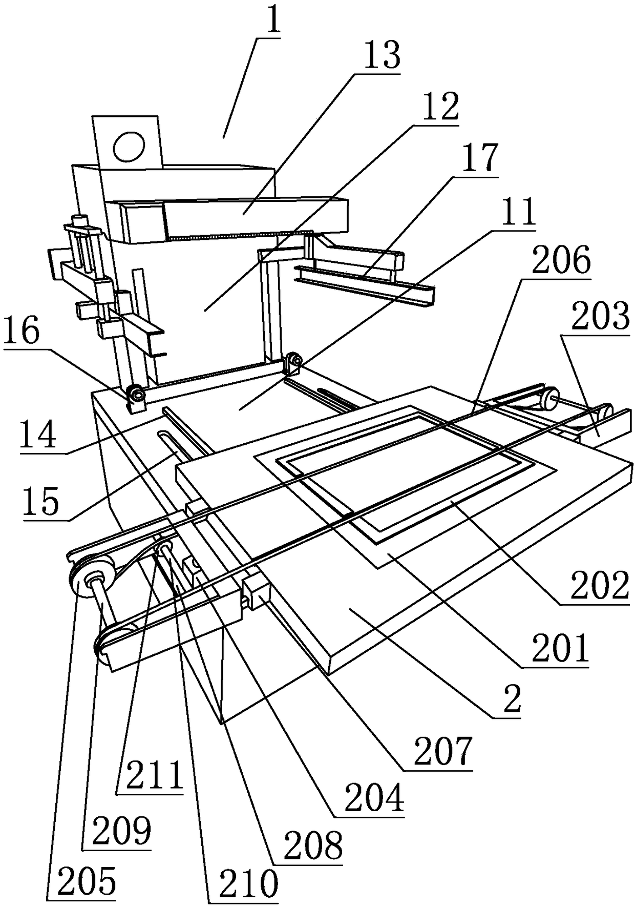
[0013] refer to figure 1 , a movable workbench of a screen printing machine with a conveyor belt according to the present invention includes a workbench 2 arranged on a screen printing machine 1, and the screen printing machine 1 includes a carrying platform 11 and a machine column 12 arranged at the rear of the carrying platform 11 , the machine column 12 is provided with a screen printing device 13 that moves up and down, the carrying platform 11 is provided with two guide rails 14 in the front and rear directions, and the bottom of the workbench 2 is provided with a chute corresponding to the guide rails 14, There are bar-shaped holes 15 on the carrying platform 11 on the outside of the two guide rails 14, that is, the left side of the left guide rail 14 and the right side of the right guide rail 14 are all provided with a bar-shaped hole 15, and the carrying platform 11 below the bar-shaped hole 15 A driving device is provided inside, the output end of the driving device i...


PUM


Abstract

The invention discloses a screen printer movable workbench with a conveying belt. The screen printer movable workbench comprises a workbench arranged on a screen printer; the screen printer comprisesa bearing platform and a column arranged at the rear part of the bearing platform; a screen printing device moving up and down is arranged on the column; at least two front-back guide rails are arranged on the bearing platform; sliding chutes correspondingly matching the guide rails are formed in the bottom of the workbench; two sides of the workbench are in pivot joint with swing arms; air cylinders for driving the swing arms to swing up and down are also arranged on two sides of the workbench; at least two roller wheels are arranged at the outer end of each swing arm; the conveying belt sleeves corresponding rollers on the two sides; a drive roller driven by a motor is also arranged at the output end of a drive device; the lower part of the conveying belt passes through a strip-shaped hole to sleeve the drive roller; a conveying belt slot matching the conveying belt in width and depth is formed in the workbench. Through the structure, the automation degree in conveying a PCB (printedcircuit board) is greatly improved, the trouble of manual fetching back and forth is avoided, the working efficiency is remarkably increased, and the labor intensity of workers is reduced.

Description

technical field [0001] The invention relates to the technical field of circuit boards, in particular to a PCB board silk screen printing device. Background technique [0002] PCB board, also known as printed circuit board, is a provider of electrical connections for electronic components, including single-panel and double-panel. The existing PCB screen printing machine has a fixed workbench and a small upper and lower space. When printing double-panel , after one side is printed, it is difficult to turn over when the other side needs to be printed, which is very inconvenient and not conducive to the printing of double-sided panels; in addition, the automation of the existing workbench for conveying PCB boards is too low, and manual work is required to continuously take them back and forth take, which greatly affects work efficiency and increases the labor intensity of workers. Therefore, it is necessary to improve and optimize the existing silk screen printing machine for P...

Claims


Application Information

Patent Timeline
IPC IPC(8): B41F15/18H05K3/12
CPCH05K3/1216B41F15/18
Inventor 詹贵全
Owner 鹤山市泰利诺电子有限公司
Learn More