
Charging facility control method, system, main controller and controller

A charging facility and control system technology, applied in charging stations, current collectors, electric vehicle charging technology, etc., can solve the problems of single type of AC-DC power module, poor system portability and compatibility, etc., to enhance system compatibility , the effect of easy system transplantation

Pending Publication Date: 2018-06-01
特瓦特能源科技有限公司
View PDF0 Cites 3 Cited by
  • Summary
  • Abstract
  • Description
  • Claims
  • Application Information

AI Technical Summary

Problems solved by technology

[0002] The current charging facilities, such as the AC-DC power module in the power cabinet of the charging pile, have a single type, and for small cars and large buses, only one type of vehicle can be satisfied
And because the charging pile may use power modules provided by multiple manufacturers, every time the power module is replaced, the power cabinet control program of the charging facility control system must be rewritten, so a lot of repetitive work has been done virtually, and the system’s Poor portability and compatibility

Method used


Image

  • Charging facility control method, system, main controller and controller
  • Charging facility control method, system, main controller and controller
  • Charging facility control method, system, main controller and controller

Examples


Embodiment Construction

[0064] The following will clearly and completely describe the technical solutions in the embodiments of the present invention with reference to the accompanying drawings in the embodiments of the present invention. Obviously, the described embodiments are only some, not all, embodiments of the present invention. Based on the embodiments of the present invention, all other embodiments obtained by persons of ordinary skill in the art without making creative efforts belong to the protection scope of the present invention.

[0065] First of all, it needs to be explained that the charging facility referred to in the embodiment of the present invention can be a facility for charging electric drive equipment in various charging scenarios. Currently, there are more widely on the market: charging piles and charging piles composed of charging piles. Stand and wait.

[0066] figure 1 It is a structural schematic diagram of a charging facility control system. Such as figure 1 As shown,...


PUM


Abstract

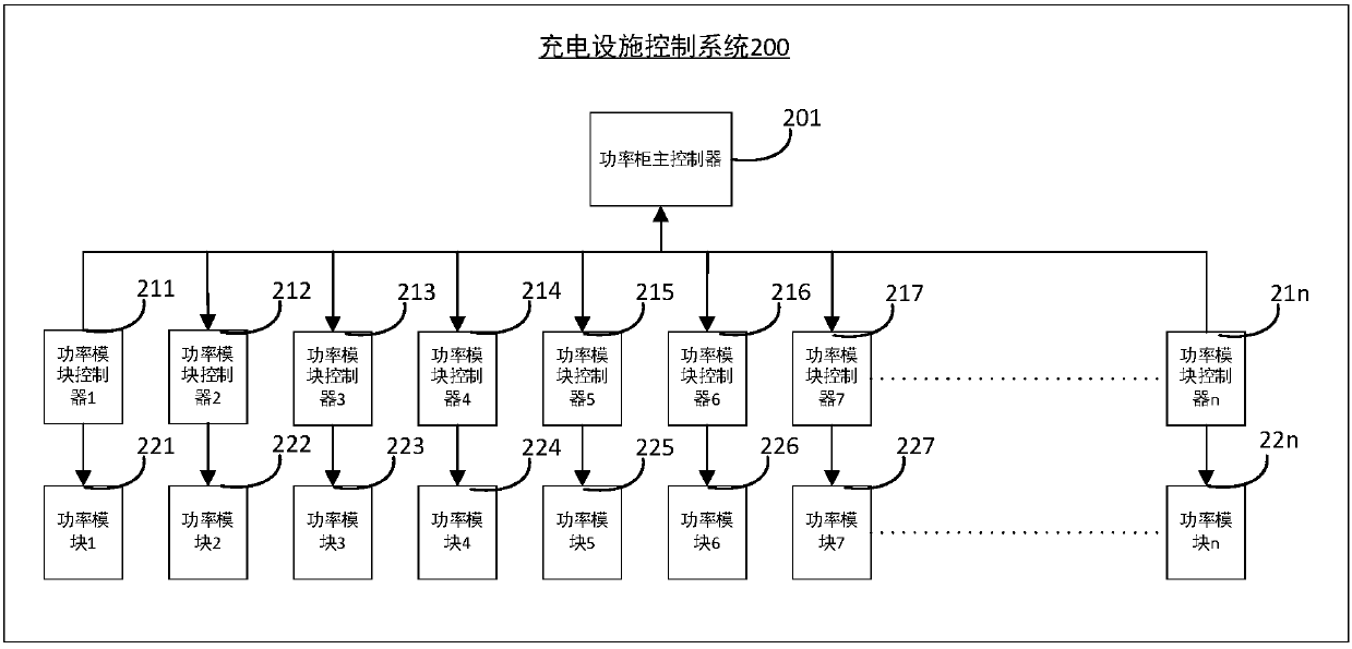
The embodiment of the invention provides a charging facility control method, system, main controller and controller, so as to enable a charging facility to recognize an AC-DC power module in a power cabinet, select a corresponding power module according to the type of an electric vehicle, distribute corresponding power and improve the portability and the compatibility of the charging facility control system. The above charging facility control system can comprise a power cabinet main controller, two or more than three power module controllers and two or more than three power modules, wherein the power cabinet main controller is used for judging the type of an electric vehicle connected to the charging facility control system, selecting a power module controller which needs to be started according to the type of the electric vehicle and sending a control instruction to the selected power module controller; and the two or more than three power module controllers are connected with the power cabinet main controller for receiving the control instruction of the power cabinet main controller and sending a power module control instruction to a power module under the jurisdiction.

Description

technical field [0001] The present invention relates to the technical field of charging facilities, in particular to a charging facility control method, system, main controller and controller. Background technique [0002] The current charging facilities, such as the AC-DC power module in the power cabinet of the charging pile, have a single type, and for small cars and large buses, only one type of vehicle can be satisfied. And because the charging pile may use power modules provided by multiple manufacturers, every time the power module is replaced, the power cabinet control program of the charging facility control system must be rewritten, so a lot of repetitive work has been done virtually, and the system’s Poor portability and compatibility. Contents of the invention [0003] The purpose of the embodiments of the present invention is to provide a charging facility control method, system, main controller and controller, so that the charging facility can identify the A...

Claims


Application Information

Patent Timeline
IPC IPC(8): H02J7/00H02J7/02B60L11/18
CPCH02J7/022H02J7/0013B60L53/20B60L2210/30H02J2207/20Y02T10/70Y02T10/7072Y02T90/14
Inventor 张增霖赵立永王昊明王昊月王亮李嘉张海亮倪维东
Owner 特瓦特能源科技有限公司
Learn More