
Sliding type lock catch device

A locking device, sliding technology, applied in the direction of ground installation, fixing device, transportation and packaging, etc., can solve the problems of time-consuming assembly and disassembly, gaps in objects to be locked, high processing cost, etc., and achieve easy replacement, easy installation, and device structure simple effect

Inactive Publication Date: 2018-06-01
JIANGXI HONGDU AVIATION IND GRP
View PDF8 Cites 2 Cited by
  • Summary
  • Abstract
  • Description
  • Claims
  • Application Information

AI Technical Summary

Problems solved by technology

Patent CN103032427A relates to a lock component, which realizes seamless connection, and is used to solve the problems of complex structure of the existing lock component, time-consuming assembly and disassembly, need for many tools, and gaps in objects to be locked
Patent CN202326554U relates to a lock buckle, which is movable, and the installation of the lock buckle and the cassette does not require bending one end of the cassette, which solves the problems of low firmness and practicability and high processing cost
Due to structural limitations and problems in the field of use, the above-mentioned patents are not suitable for solving the opening and closing problem of the pedals of the random pedal boarding device

Method used


Image

  • Sliding type lock catch device
  • Sliding type lock catch device
  • Sliding type lock catch device

Examples


Embodiment Construction

[0019] It should be noted that "up, down, left, and right" in this embodiment are all described according to the drawings, and are not limitations of the present invention. The location can be set according to specific requirements.

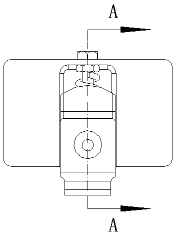
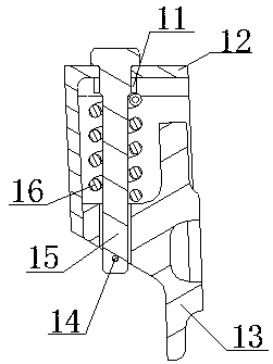
[0020] Attached below Figure 1-6 The present invention is described in further detail: as Figure 1-3 As shown, a sliding locking device is installed on the structure of the fuselage skin 3, and is used to limit the rotation of the pedal 2 and control its opening and closing. The locking device includes a nut 11, a lock seat 12, a lock Buckle 13, latch 14, special bolt 15, spring 16; Wherein, special bolt 15 is " T " font, comprises the bolt head 151 that is parallel with the outer surface of lock seat and the bolt body that vertically arranges, and bolt body is close to bolt head 151 One end of one end is provided with thread 152, and the rest is polished rod 153, and the diameter of thread 152 is greater than the diameter of polished rod 153...


PUM


Abstract

The invention relates to a lock catch device used in cooperation with a pedal. A sliding type lock catch device is installed on a fuselage skin structure and is used for limiting rotation of the pedaland controlling the pedal to be opened and closed; the lock catch device comprises a special bolt, a lock base, a nut, a lock catch and a spring; the special bolt is in the type of T, and comprises abolt head matched with the outer surface of the lock base and a vertically arranged bolt body; the end, close to the bolt head, of the bolt body is provided with a thread, and the remaining portion is an unthreaded rod; the bolt body penetrates a through hole formed in the top end of the lock base; the nut is matched with the thread of the special bolt, and is used for fixing the special bolt tothe lock base; the lock catch comprises an open hole containing the unthreaded rod and used for the unthreaded rod to pass through and a lock catch stretch-out part clamped to a pedal clamping groove;the lock catch moves up and down along the unthreaded rod; the spring is arranged on the unthreaded rod in a sleeving manner; one end of the spring abuts against the nut, and the other end of the spring abuts against the lock catch; and the end portion of the unthreaded rod is provided with a limiting part preventing the lock catch from disengaging. The lock catch device has the following beneficial effect that the device structure is simple, the lock catch is easy to replace, installing is convenient, and aviators or ground staff can manually start the airplane pedal conveniently to get on or off a plane.

Description

technical field [0001] The invention relates to a locking device used in conjunction with a pedal, belonging to the field of aircraft structure design. Background technique [0002] Pilots or ground crew need to use boarding devices to get on and off the plane. The boarding devices include conventional boarding ladders and random boarding ladders. A certain type of aircraft is equipped with random pedal boarding devices without affecting the overall aerodynamic performance. The pedals It can be opened and closed by rotating up and down around the rotating shaft. Since one end of the pedal is in contact with the compression spring, in order to prevent the pedal from being automatically opened by the elastic force and affecting the flight safety of the aircraft, it is necessary to limit it with the help of a locking device to control the movement of the pedal. On and off. Patent CN103032427A relates to a lock assembly, which realizes seamless connection, and is used to solve ...

Claims


Application Information

Patent Timeline
IPC IPC(8): F16B1/02B64F1/315
CPCF16B1/02B64F1/315
Inventor 张勇王强王建华余志明陈里根袁平湘朱媛许小妹江鹏林雷鄢仁浙程广林
Owner JIANGXI HONGDU AVIATION IND GRP
Learn More