


Quick Research
Generate reliable direction feasibility study reports for your R&D in just a few steps.

Technical Q&A
Discover and master advanced knowledge NOW. Basics, ideas, possibilities, all at once.

Find Solutions
As an expert in R&D theories, this can generate solutions to your technical problems instantly.

Evaluate Feasibility
Analyze your overall solution with one click, know your potential R&D risks in advance.

Monitor Landscape
Get weekly tech updates, stay abreast of the latest tech innovations and key insights.
Control method of circuit system of counting and stacking machine
A circuit system and control method technology, applied in the direction of conveyor control device, conveyor, object stacking, etc., can solve the problems of easily polluted blade surface, error-prone counting, easy to be scratched, etc., to achieve high safety, Accurate counting and high efficiency
- Summary
- Abstract
- Description
- Claims
- Application Information
AI Technical Summary
Problems solved by technology
Method used
Image

Examples
Embodiment 1
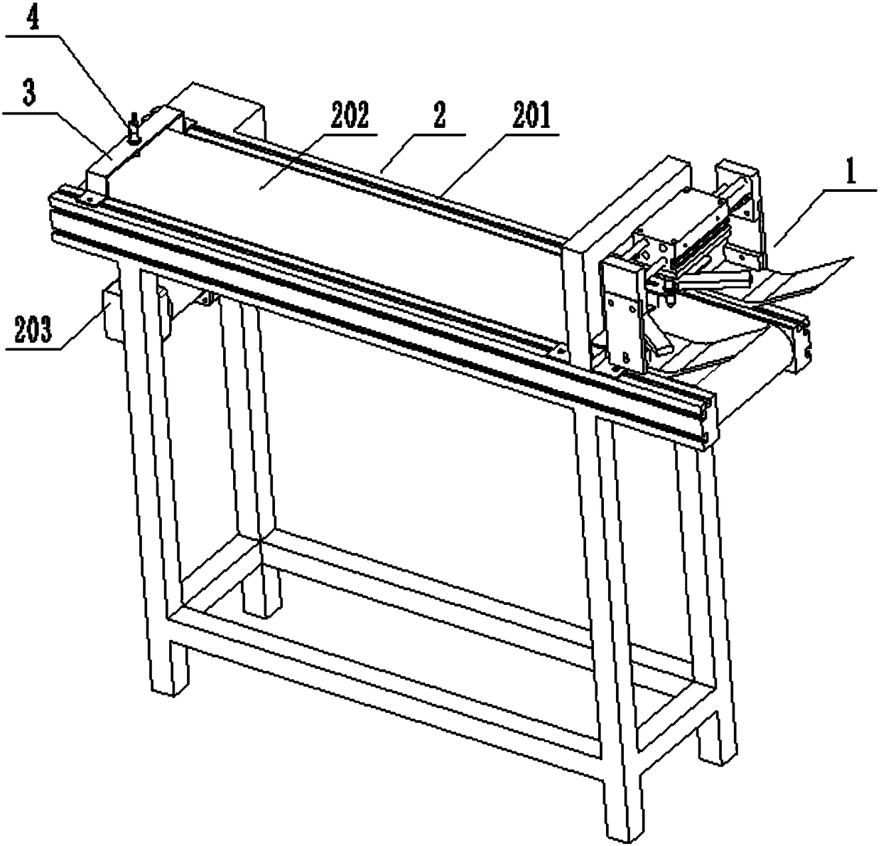
[0051] Such as figure 1 As shown, an automatic cloth measuring code machine of this embodiment includes a cloth mechanism 1 and a conveying mechanism 2; wherein, as a solution of this embodiment, the conveying mechanism 2 is a belt conveyor, which includes a frame and a set A pair of beams 201 on the frame, a belt 202 is installed by a drum between a pair of beams 201, a motor 203 is installed on the frame, and the motor 203 is connected with the drum through a reduction box, thereby driving the drum to rotate and driving the belt 202 to move. Of course, the use of a belt conveyor for the conveying mechanism 2 is only a preferred mode of this embodiment, and other structures in the prior art can also be used, as long as the conveying function can be realized. In this embodiment, the upper surface of the beam 201 is provided with a T-shaped groove, which facilitates the detachable installation of other components, and the position can be adjusted at will.
[0052] Described ma...
Embodiment 2
[0057] When the material does not need to enter the next process, the stacking of the material on the conveying mechanism 2 may exceed its stroke, and the problem of material drop occurs. Based on this premise, the automatic cloth measuring machine of this embodiment is based on the structural basis of embodiment On the conveying mechanism 2, a limit proximity switch 4 is set at the end away from the cloth mechanism 1, which is used to sense the limit position of the material conveyed by the conveying mechanism 2. The limit proximity switch 4 is fixed by the switch holder 3 installed on the beam 201. During use, the limit proximity switch 4 senses the material, and sends a signal to the control unit to stop the conveying mechanism 2 and continue to transport forward. At this time, the materials on the conveying mechanism 2 can be packed into boxes and other operations.
Embodiment 3
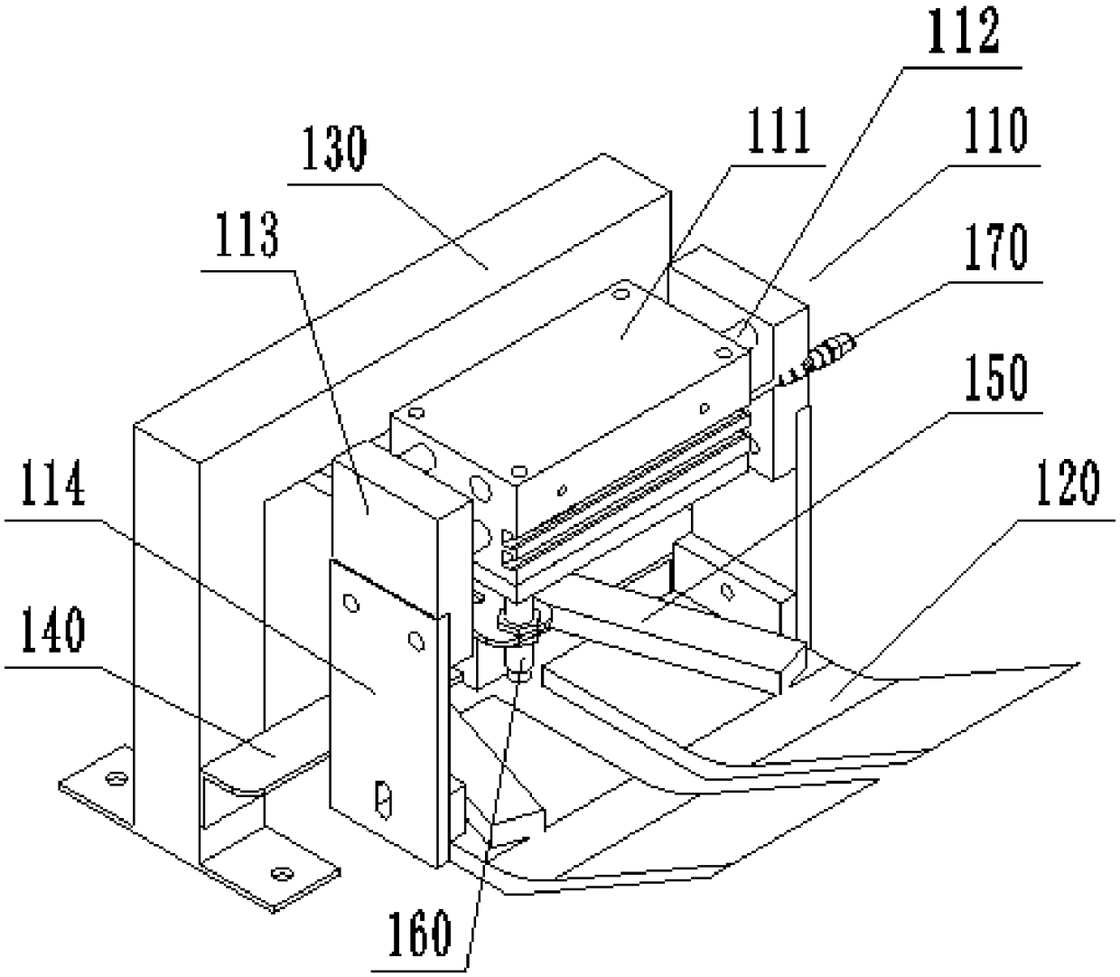
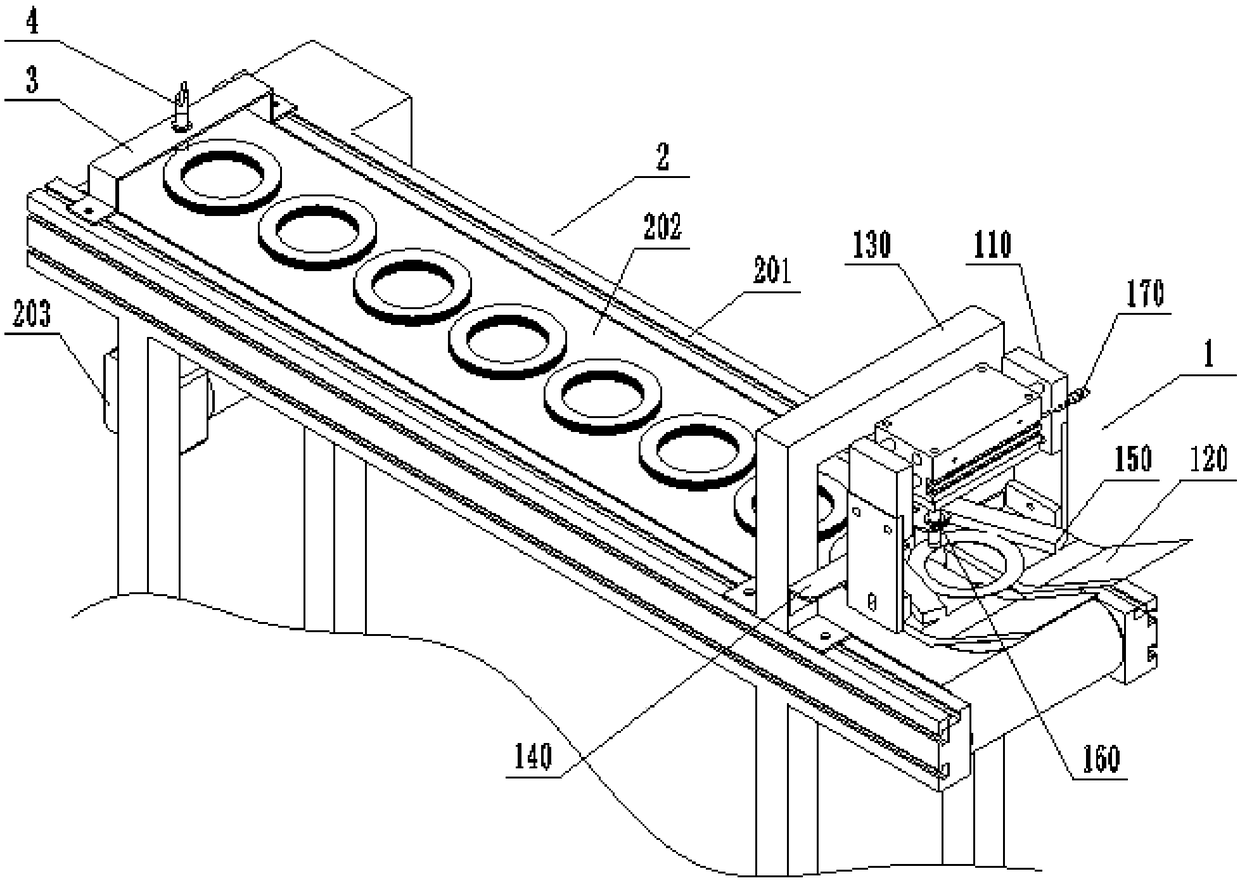
[0059] This embodiment provides a control method for an automated cloth measuring coder, which is used to control and use the cloth measuring coder in Embodiment 2 to perform palletizing operations of metal circular blades, combined with image 3 and Figure 4 As shown, the specific steps are as follows: firstly, the drive cylinder 110 of the material distribution mechanism 1 drives the material receiving plate 120 to draw in, that is, the piston rods 112 on both sides of the cylinder body 111 shrink, and the fingers 113 drive the two material receiving plates 120 to approach each other to achieve gathering. Then, the blade falls on the material receiving plate 120, and is stuck between two material stoppers 150, and is received and positioned. At the same time, the cloth proximity switch 160 senses the blade, generates an electrical signal and transmits the control element, and the control element controls The drive cylinder 110 moves, the piston rod 112 of the drive cylinder...
PUM
 Abstract
Description
Claims
Application Information
 - R&D Engineer
- R&D Manager
- IP Professional
- Industry Leading Data Capabilities
- Powerful AI technology
- Patent DNA Extraction
Browse by: Latest US Patents, China's latest patents, Technical Efficacy Thesaurus, Application Domain, Technology Topic, Popular Technical Reports.
© 2024 PatSnap. All rights reserved.Legal|Privacy policy|Modern Slavery Act Transparency Statement|Sitemap|About US| Contact US: help@patsnap.com