
Gravity transmission system

A transmission system and gravity technology, applied in conveyors, conveyor objects, mechanical conveyors, etc., can solve the problems of complex structure, high manufacturing cost and long design cycle of motor drive system and chain drive system, and achieve simple structure, Low manufacturing cost and low cost effect

Pending Publication Date: 2018-06-01
COMAU SHANGHAI ENG
View PDF6 Cites 6 Cited by
  • Summary
  • Abstract
  • Description
  • Claims
  • Application Information

AI Technical Summary

Problems solved by technology

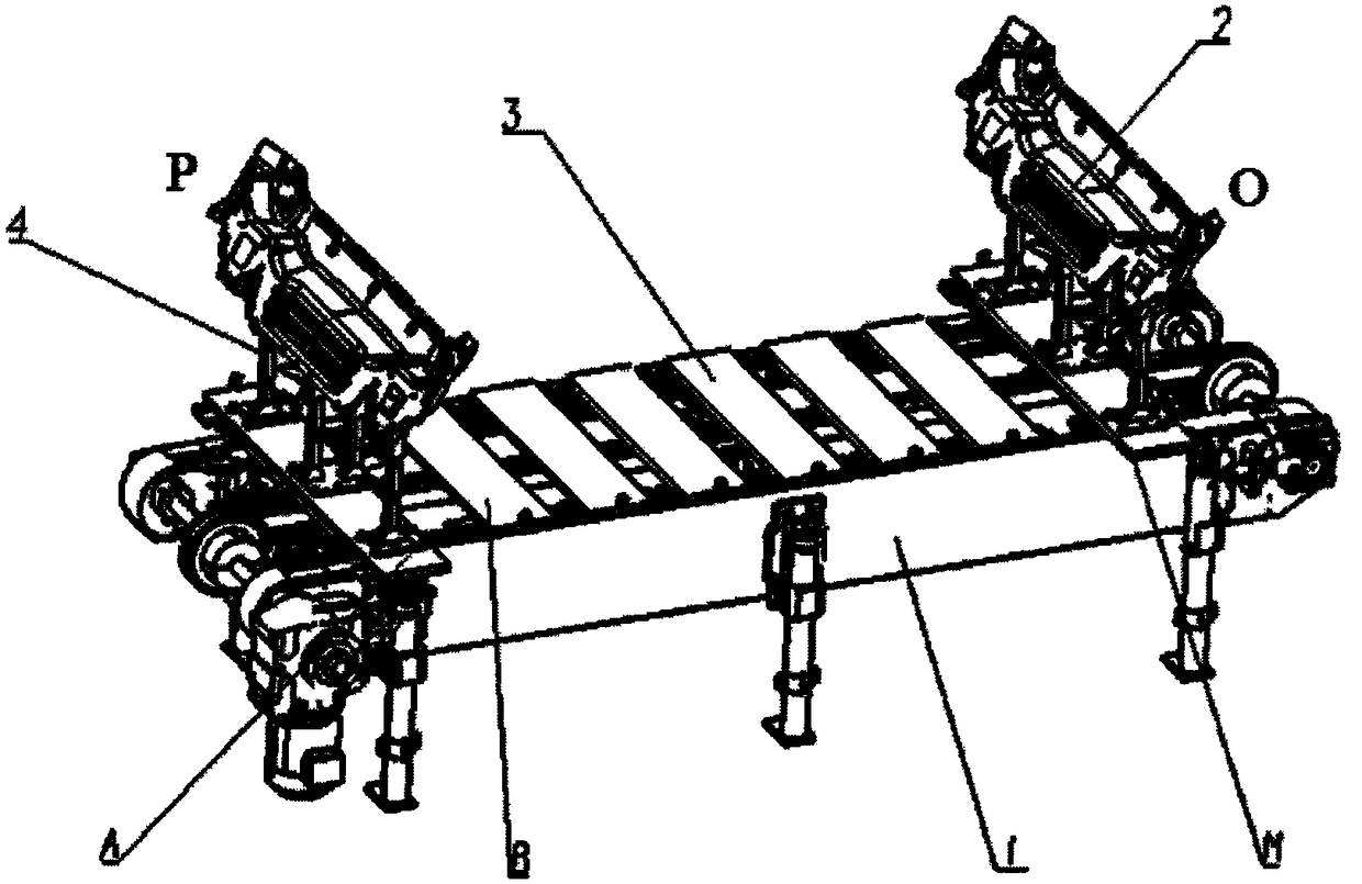
[0005] The above-mentioned existing accumulation type pallet conveyor 1 has the following defects: the structure of the motor drive system and the chain drive system is complex, the design period is long, the manufacturing cost is high, and maintenance is inconvenient

Method used


Image

  • Gravity transmission system
  • Gravity transmission system
  • Gravity transmission system

Examples


Embodiment Construction

[0026] Below in conjunction with specific embodiment, further illustrate the present invention.

[0027] figure 2 It is a schematic diagram of the gravity transmission system provided in this embodiment, and the gravity transmission system is composed of a frame 5, a tray mechanism 6, a deceleration mechanism 7, a blocking mechanism 8, a pneumatic turning mechanism 9, and the like.

[0028] Frame 5 both sides are provided with guide rail 14, and guide rail 14 adopts hexagonal steel guide rail. The guide rail 14 comprises a forward transport guide rail 14-1 located above the frame 5 and a return guide rail 14-2 located below the frame 5, the forward transport guide rail 14-1 is inclined downward along the transport direction Z, and the return guide rail 14-2 is inclined downward along the return direction R slopes down. The two ends of the frame 5 are point O (upstream along the transport direction Z) and point P (downstream along the transport direction Z) of the loading po...


PUM


Abstract

The invention provides a gravity transmission system. Guide rails are arranged on the two sides of a frame, and each guide rail comprises a forward transportation guide rail and a returning guide railwhich are located over the frame and located under the frame respectively; the forward transportation guide rails incline downwards in the transportation direction, the returning guide rails inclinedownwards in the returning direction, and the two ends of the forward transportation guide rails and the two ends of the returning guide rails are connected through arc transition tracks; a tray mechanism is arranged on the guide rails of the frame and can slide along the guide rails; the upper portion, in the transportation direction, of the end of the frame serves as a feeding station, and the lower portion, in the transportation direction, of the end of the frame serves as a working station; pneumatic turning mechanisms used for conveying the tray mechanism to the forward transportation guide rails from the returning guide rails are arranged at the joints of the forward transportation guide rails and the returning guide rails which are located at the feeding station; and the feeding station, the working station and the to-be-turned station of the frame are each provided with a blocking mechanism used for blocking the tray mechanism from advancing. According to the gravity transmission system, the structure is simple, the manufacturing cost is low, and maintenance is easy; power is supplied to transmission through the gravity, and additional driving force does not need to be supplied; and external energy sources are not consumed, and energy conservation and environment protection are achieved.

Description

technical field [0001] The invention relates to a gravity transmission system, which is used for the transmission of workpieces or tooling parts on a production line, and belongs to the field of manufacturing technology. Background technique [0002] In the field of manufacturing technology, it is often necessary to remove workpieces or tooling parts from bins or racks, and transport them to a specific position on the production line that can be picked up by workers or within the reach of robots according to a predetermined position and direction. In order to carry out the next step of gluing, loading and other processes, it is necessary to use certain transmission equipment to realize the above transmission functions. [0003] figure 1 Shown is a typical transmission equipment in the field of automobile manufacturing technology, that is, the accumulation type pallet conveyor 1, the body panel 2 is positioned and lifted by the positioning tool 4 fixed on the pallet 3; when ...

Claims


Application Information

Patent Timeline
Patent Type & Authority Applications(China)
IPC IPC(8): B65G35/00B65G47/88B65G47/248B65G47/26
CPCB65G35/00B65G47/248B65G47/26B65G47/8823B65G2201/0258
Inventor 袁先杰杨旭左春张振东于坤坤
Owner COMAU SHANGHAI ENG
Learn More