Modularized surface-mount type permanent magnet rotor

A permanent magnet, surface-mounted technology, applied in the direction of magnetic circuit rotating parts, magnetic circuit, magnetic circuit shape/style/structure, etc. Problems such as difficult processing of permanent magnets, to avoid the decline of glue adhesion, simple processing, and firm fixation

Pending Publication Date: 2018-05-29
沈阳蓝光驱动技术有限公司
View PDF4 Cites 0 Cited by
  • Summary
  • Abstract
  • Description
  • Claims
  • Application Information

AI Technical Summary

Problems solved by technology

[0007] The purpose of the present invention is to provide a modular surface-mounted permanent magnet rotor, which solves the difficulties in processing the permanent magnets of the permanent magnet synchronous motor rotor, high cost, and the surface-mounted permanent magnets of the rotor sleeve are not fixed firmly and cannot withstand large torques. Technical problems, its structural design is reasonable, the processing of parts is simple, the permanent magnet is firmly fixed, the rotor sleeve module unit is easy to assemble, and it is easy to meet the adjustment requirements of the large torque of the motor. The operation is reliable and stable, and the production and maintenance costs are reduced.

Method used


Image

  • Modularized surface-mount type permanent magnet rotor
  • Modularized surface-mount type permanent magnet rotor
  • Modularized surface-mount type permanent magnet rotor

Examples


Embodiment Construction

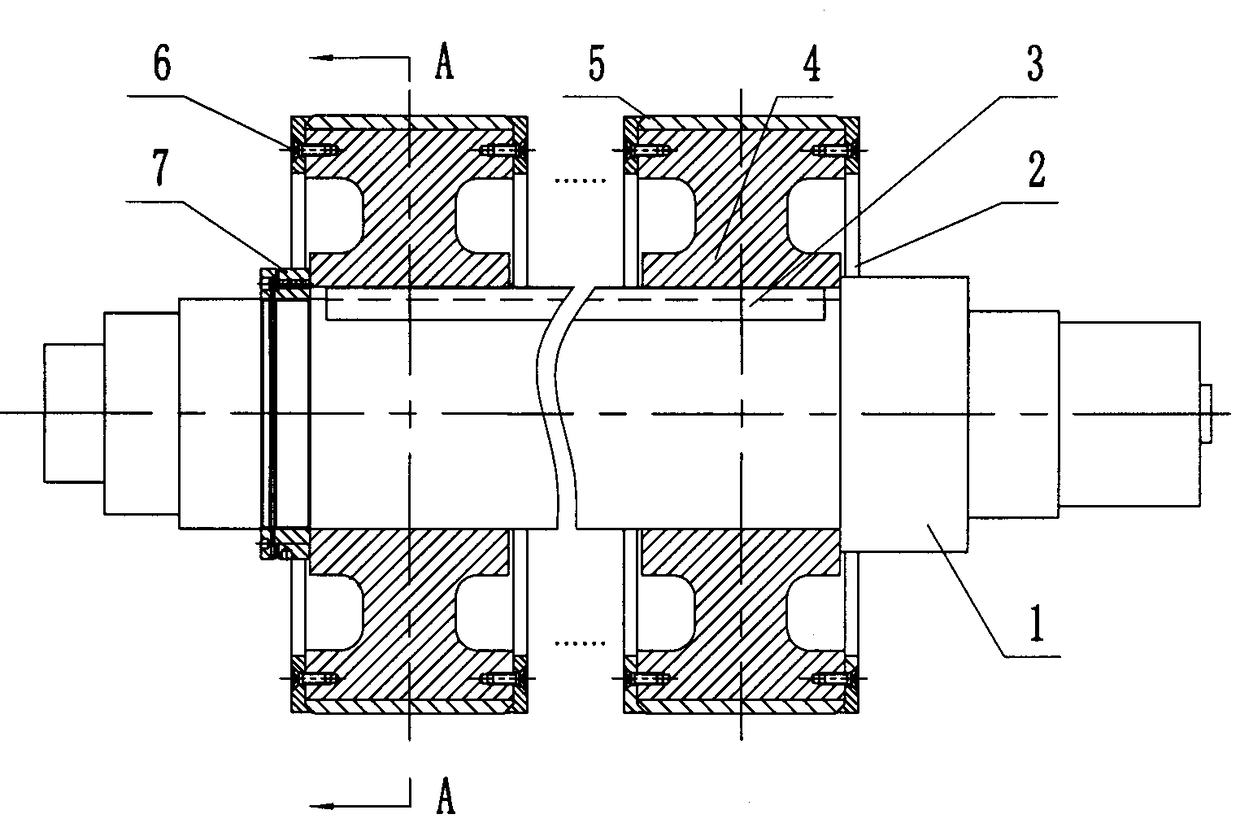
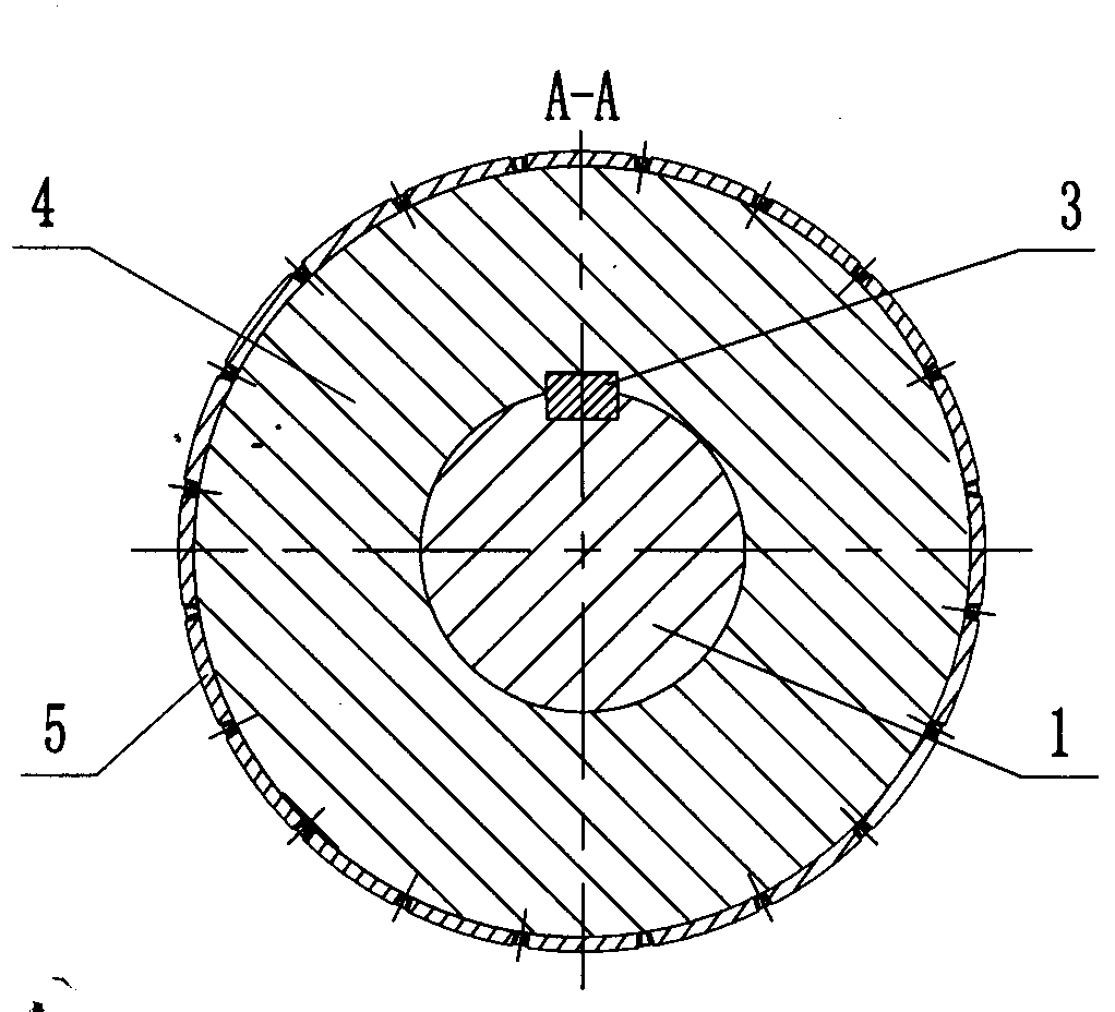
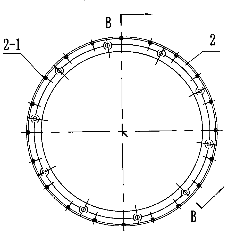
[0021] according to Figure 1-7 The specific structure of the present invention will be described in detail. The modular surface-mounted permanent magnet rotor includes a main shaft 1 and components such as a rotor module unit assembled on the main shaft 1 by means of a flat key 3 and a lock nut 7 . Wherein, at least one rotor module unit is assembled on the main shaft 1 . Each rotor module unit can be composed of a rotor sleeve 4 assembled together, a plurality of permanent magnets 5 , two clips 2 and fasteners 6 to form an integrated structure. Therefore, according to the high torque of the motor, the number of rotor module units can be assembled arbitrarily, and the output torque of the motor can be increased, which solves the technical problem that the surface-mounted permanent magnet cannot be firmly fixed due to the high torque required by the motor. Fasteners 6 may consist of countersunk screws. The outer periphery of the buckle 2 is provided with conical stops evenl...


PUM


Abstract

Provided is a modularized surface-mount type permanent magnet rotor, which resolves the technical problems that permanent-magnet synchronous motor is difficult in processing and high in cost, and thesurface-mount type fixing between a rotor sleeve and the permanent magnet is not stable, and high torque cannot be born. The modularized surface-mount type permanent magnet rotor comprises a main shaft and a rotor module unit assembled to the main shaft. The modularized surface-mount type permanent magnet rotor is characterized in that the main shaft is at least assembled with a rotor module unit;the periphery of a buckle piece of the rotor module unit is provided with a conical baffle bench of a wedge-shaped jaw, and the inner conical surface of the conical baffle bench matches with the inclined plane of the end part of a permanent magnet arc surface; with the buckle pieces fixed to two ends of a rotor sleeve, the permanent magnet can be arranged on a cylindrical surface of the rotor sleeve in a surface-mount manner; the inner conical surface of the conical baffle bench of the buckle piece presses tightly against the inclined plane of the permanent magnet, and the wedge-shaped claw disposed at the baffle bench of the buckle piece can be clamped tightly between two adjacent permanent magnets. The modularized surface-mount type permanent magnet rotor is advantageous in that the structure is reasonable in design, components are simple in processing, and the permanent magnet is stable in fixing; the formed rotor sleeve module unit is convenient in assembling; the adjusting demandof large torque of motor can be met; running is reliable and stable, and producing and maintenance cost can be reduced.

Description

technical field [0001] The invention relates to a permanent magnet synchronous motor rotor, in particular to a modular surface-mounted permanent magnet rotor for a large-torque inner rotor permanent magnet synchronous motor. It is suitable for technical fields such as oil fields, metallurgy, and mines. Background technique [0002] With the continuous advancement of science and technology, permanent magnet synchronous motors are continuously applied to fields such as oil fields, metallurgy, and mines. The motors in these fields are characterized by high torque. If the motor rotor still uses the traditional permanent magnet embedded structure, a large number of The use of rotor punching increases the manufacturing cost. As permanent magnet synchronous motors are required to output more and more torque, the firmness of surface-mounted permanent magnets will affect the reliability and stability of motor operation and become an extremely prominent problem. [0003] In order to...

Claims


Application Information

Patent Timeline
IPC IPC(8): H02K1/27
CPCH02K1/2706
Inventor 梁丙雪徐广人王东剑廖国华董胜波黄丽
Owner 沈阳蓝光驱动技术有限公司
Why Eureka
Try Eureka