
Efficient condenser

A condenser and high-efficiency technology, applied in the direction of evaporator/condenser, refrigerator, refrigeration components, etc., can solve the problems of low condensation efficiency, large size, and high cost of the condenser, and achieve improved condensation efficiency, improved condensation efficiency, and heat dissipation fast effect

Inactive Publication Date: 2018-05-29
博维恩冷冻科技(苏州)有限公司
View PDF4 Cites 1 Cited by
  • Summary
  • Abstract
  • Description
  • Claims
  • Application Information

AI Technical Summary

Problems solved by technology

However, for the condenser with the above structure, the heat of the high-temperature gas or steam flowing in the tube body needs to be transferred to the tube body first, then transferred to the heat dissipation shell by the tube body, and then transferred to the surrounding by the heat dissipation shell. The air is finally discharged, and the heat of high-temperature gas or steam cannot be directly transferred to the air through the heat dissipation shell, so the condensation efficiency of this kind of condenser is very low, and generally the shape of the heat dissipation shell can only be enlarged by extending the length of the tube body To enhance its condensation effect, it is bulky and expensive

Method used


Image

  • Efficient condenser

Examples


Embodiment Construction

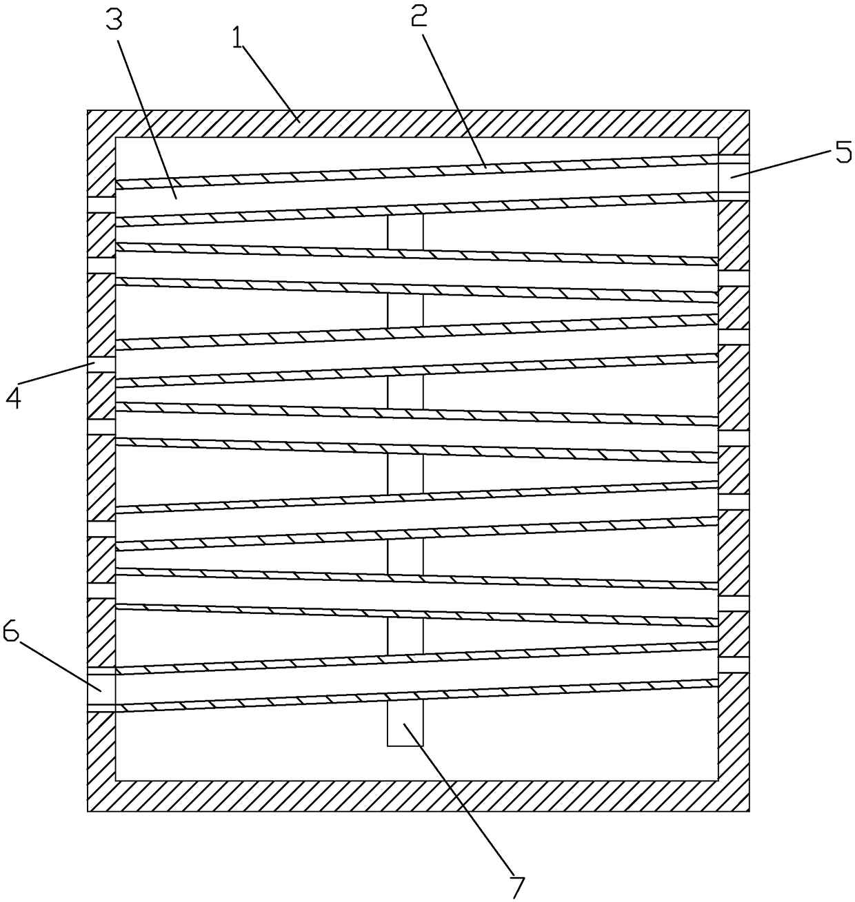
[0022] A high-efficiency condenser provided in this embodiment has a structure such as figure 1 shown.

[0023] The high-efficiency condenser includes an outer shell 1 and several inner shells 2 evenly distributed inside the outer shell 1 from top to bottom. The inner casing 2 is arranged obliquely and the included angle range with the horizontal direction is 15-30°, and the inclination directions of the inner casings 2 adjacent up and down are opposite. A connecting pipe 7 communicating with each other is provided between the inner shells 2, the uppermost inner shell 2 is provided with a liquid inlet 5, and the lowermost inner shell 2 is provided with a liquid outlet 6, and the liquid inlet 5 and The liquid outlet 6 is respectively provided with an automatic liquid inlet valve and an automatic liquid outlet valve.

[0024] The two sides of the inner shell 2 are open and connected with the outer shell 1 to form a refrigerating chamber 3, the refrigerating chamber 3 is filled...


PUM


Abstract

The invention discloses an efficient condenser, and relates to the technical field of refrigeration. The efficient condenser comprises an outer shell body, and further comprises multiple inner shellswhich are uniformly distributed inside the outer shell; two side surfaces of the inner shells are open and are connected with the outer shell to form refrigerating chambers; heat dissipation holes areformed in the position, on opened positions, of the outer shell, and one-way breathable films cover the heat dissipation holes; refrigerants are arranged in the refrigeration chambers; the outer surfaces of the inner shells are tightly attached to the inner surface of the outer shell, inner grooves are formed in the outer surfaces of the inner shells, outer grooves are formed in the inner surfaceof the outer shell, wherein the inner grooves and the outer grooves form a condensation channel, and the condensation channel sequentially passes through the outer surfaces of the inner shells; and acondensation inlet and a condensation outlet are formed in the shell, and the condensation inlet communicates with one end of the condensation channel, and the condensation outlet communicates with the other end of the condensation channel. According to the efficient condenser, the condensation channel of a heat source is formed by utilizing the outer shell and the inner shell, a pipe body whichis used for circulating the heat source arranged in the outer shell is omitted, so that heat of the heat source is directly transmitted to the outer shell instead of being transmitted to the outer shell through the pipe body firstly, and therefore heat dissipation is faster, and the condensation efficiency is improved.

Description

technical field [0001] The invention relates to the technical field of refrigeration, in particular to a high-efficiency condenser. Background technique [0002] In the prior art, the condensers used, especially the condensers used in cabinet air conditioners, are mostly tubular structures, which include a heat dissipation shell, and many curved tubes are installed in the shell. In specific applications, high-temperature gas or steam or pure liquid is passed into the liquid inlet hole in the tube. During the flow process, the high-temperature gas or steam in the tube body transfers heat to the tube body, and the tube body transfers heat to the heat dissipation shell. , the heat dissipation shell then transfers the heat to the surrounding air, thereby reducing the temperature of the high-temperature gas or steam in the pipe body, making it condensed and turning into a liquid with a lower temperature, which then flows out from the liquid outlet hole of the pipe body. [0003]...

Claims


Application Information

Patent Timeline
Patent Type & Authority Applications(China)
IPC IPC(8): F25B39/04F25B49/00F28D7/00
CPCF25B39/04F25B49/00F25B2339/046F25B2700/2116F28D7/0058
Inventor 唐建明唐荣
Owner 博维恩冷冻科技(苏州)有限公司
Learn More