
Air conditioning system and control method

An air-conditioning system and electric control box technology, applied in the direction of refrigerators, refrigeration components, refrigeration and liquefaction, etc., can solve the problems of increasing system load, large heat dissipation of the main board, and poor cooling effect, so as to increase the exhaust volume, Improve system energy efficiency and increase evaporation efficiency

Active Publication Date: 2018-05-29
GREE ELECTRIC APPLIANCES INC
View PDF13 Cites 3 Cited by
  • Summary
  • Abstract
  • Description
  • Claims
  • Application Information

AI Technical Summary

Problems solved by technology

[0002] The two-stage compressor unit can provide users with hot and cold water under a wide range of operating temperature conditions to meet the user's cooling and heating requirements. However, the unit runs for a long time, and the heat dissipation of the main board is large. If the temperature is not cooled in time, it will affect the main board. The stability and service life of the main board are currently mainly air-cooled, the air-cooled cooling effect is poor, and air ducts and fans need to be installed, the structure is more complicated, and the direct use of refrigerants to directly control the temperature of the main board will lead to compression The pressure ratio of the machine becomes larger, which increases the system load

Method used


Image

  • Air conditioning system and control method
  • Air conditioning system and control method
  • Air conditioning system and control method

Examples


Embodiment Construction

[0030] In order to make the object, technical solution and advantages of the present invention clearer, the present invention will be further described in detail below in conjunction with the accompanying drawings and embodiments. It should be understood that the specific embodiments described here are only used to explain the present invention, not to limit the present invention.

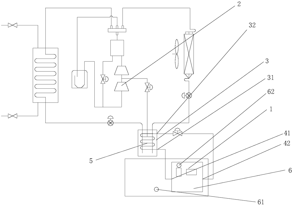
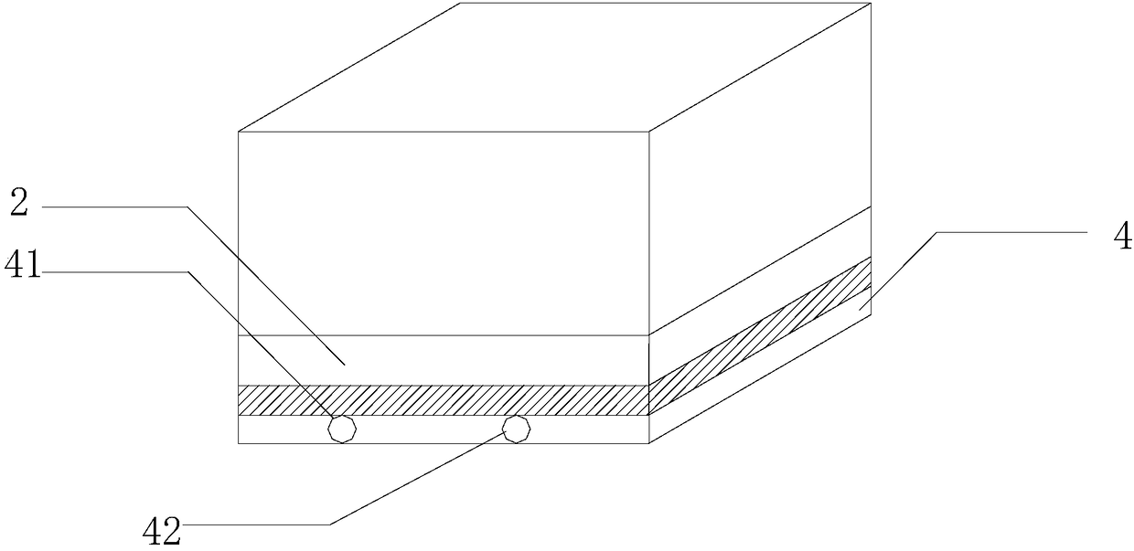
[0031] Such as Figure 1 to Figure 3 The air conditioning system shown includes a circuit board 1, a two-stage compressor 2 and a flasher 3, the two-stage compressor 2 is provided with a low-pressure inlet and a medium-pressure inlet, and the outlet of the flasher 3 is connected to the The medium pressure inlet is connected, and also includes a heat dissipation assembly 4, which is arranged on the circuit board 1, and both ends of the heat dissipation assembly 4 are connected with the flasher 3 to form a heat dissipation circulation channel, and the flashing The liquid refrigerant inside the devic...


PUM


Abstract

The invention provides an air conditioning system and a control method. The air conditioning system comprises a circuit board, a double-stage compressor and a flash generator, wherein the double-stagecompressor is provided with a low-pressure inlet and a medium-pressure inlet, and an outlet of the flash generator communicates with the medium-pressure inlet. According to the air conditioning system and the control method, a heat dissipation assembly is arranged on the circuit board, cooling is carried out by further utilizing a refrigerant gravity liquid supply mode in the flash generator, a liquid refrigerant enters the inner side of the heat dissipation assembly for heat absorption through the flash generator, the refrigerant after heat absorption is changed into gas and flows back intothe flash generator, the gas-state refrigerant can also be used for supplementing the gas and increasing the enthalpy to the two-stage compressor, so that the energy efficiency of the system is improved; and when the heat dissipation assembly communicates with a heat exchange coil pipe, sealing circulation is formed between the heat dissipation assembly of the circuit board and the heat exchange coil pipe, heat of the circuit board can be transferred into the flash generator, namely, the heat of the circuit board can be recycled, so that the evaporation efficiency in the flash generator is improved, the exhaust volume of the flash generator is increased, and the energy efficiency of the system is improved.

Description

technical field [0001] The invention relates to the technical field of air conditioning equipment, in particular to an air conditioning system and a control method. Background technique [0002] The two-stage compressor unit can provide users with hot and cold water under a wide range of operating temperature conditions to meet the user's cooling and heating requirements. However, the unit runs for a long time, and the heat dissipation of the main board is large. If the temperature is not cooled in time, it will affect the main board. The stability and service life of the main board are currently mainly air-cooled, the air-cooled cooling effect is poor, and air ducts and fans need to be installed, the structure is more complicated, and the direct use of refrigerants to directly control the temperature of the main board will lead to compression The pressure ratio of the machine becomes larger, which increases the system load. Contents of the invention [0003] In order to ...

Claims


Application Information

Patent Timeline
IPC IPC(8): F25B1/10F25B41/00F25B41/04F25B49/02F25B41/20F25B41/40
CPCF25B1/10F25B41/00F25B49/02F25B2700/21F25B2600/2519F25B2500/08F25B41/20
Inventor 尚瑞于海峰林海佳吴一梅柯彬彬
Owner GREE ELECTRIC APPLIANCES INC
Learn More