
Air purification defense system

A defense system and air purification technology, applied in air conditioning systems, space heating and ventilation, space heating and ventilation details, etc., can solve problems such as loud noise, limited water volume of fog cannons, etc., and achieve the effect of prolonging the service life

Pending Publication Date: 2018-05-29
宙斯流体系统(上海)有限公司
View PDF0 Cites 9 Cited by
  • Summary
  • Abstract
  • Description
  • Claims
  • Application Information

AI Technical Summary

Problems solved by technology

[0002] In recent years, smog has become an environmental problem that plagues most regions in China. For smog control, the emission of exhaust gas can be reduced from the source, such as restricting production at construction sites, restricting the use of cars, and restricting factory emissions. At the same time as emissions, the needs of production and the needs of residents’ lives must also be taken into account. Therefore, the problem of smog is still relatively serious. For the smog that has occurred, people have developed a large number of products to control it, such as the fog cannon vehicles that are often used today. , but the fog cannon vehicle can only control the environment on the road in a small range, and for schools, hospitals, communities and other areas, there are many inconveniences in using the fog cannon vehicle. For example, the height controlled by the fog cannon vehicle is limited by the spray height. It can only purify the air within a few meters, and the fog cannon vehicle cannot meet the needs of residents living in high-rise buildings for clean air. At the same time, a large amount of exhaust gas is discharged and a large noise is generated.

Method used


Image

  • Air purification defense system
  • Air purification defense system
  • Air purification defense system

Examples


Embodiment 1

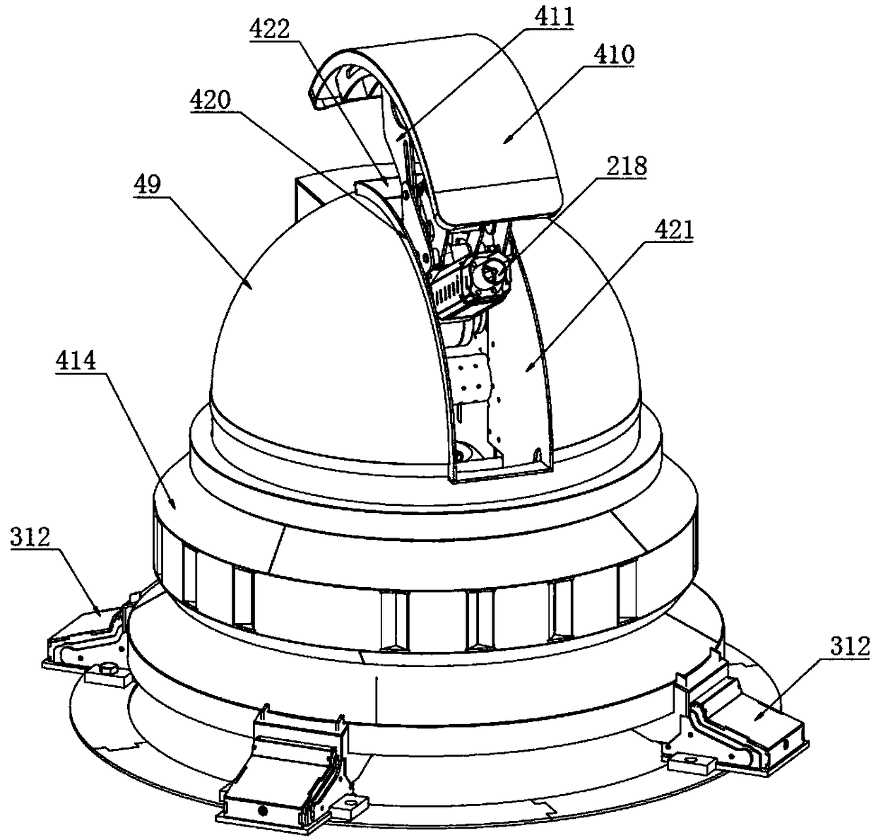
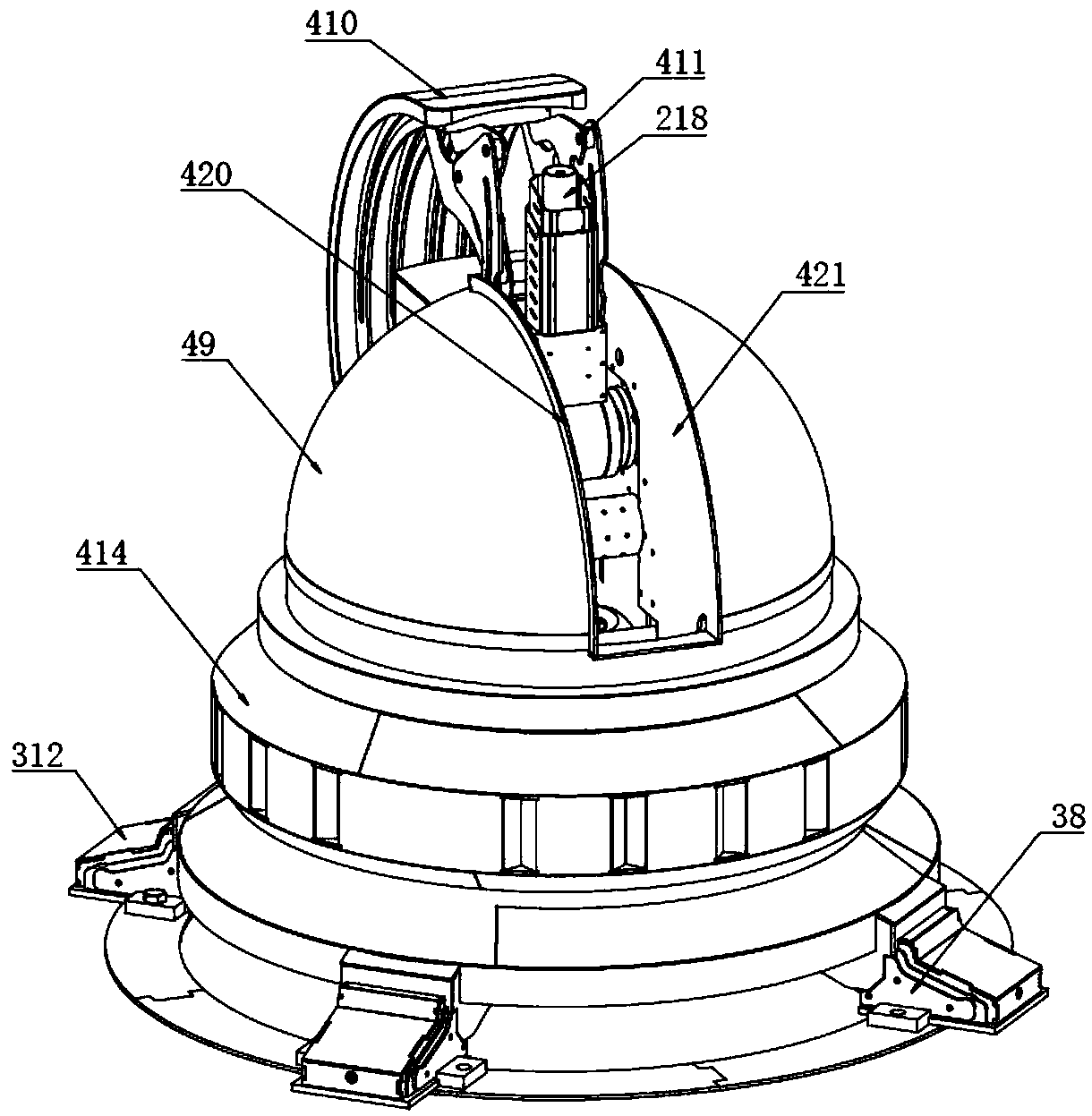
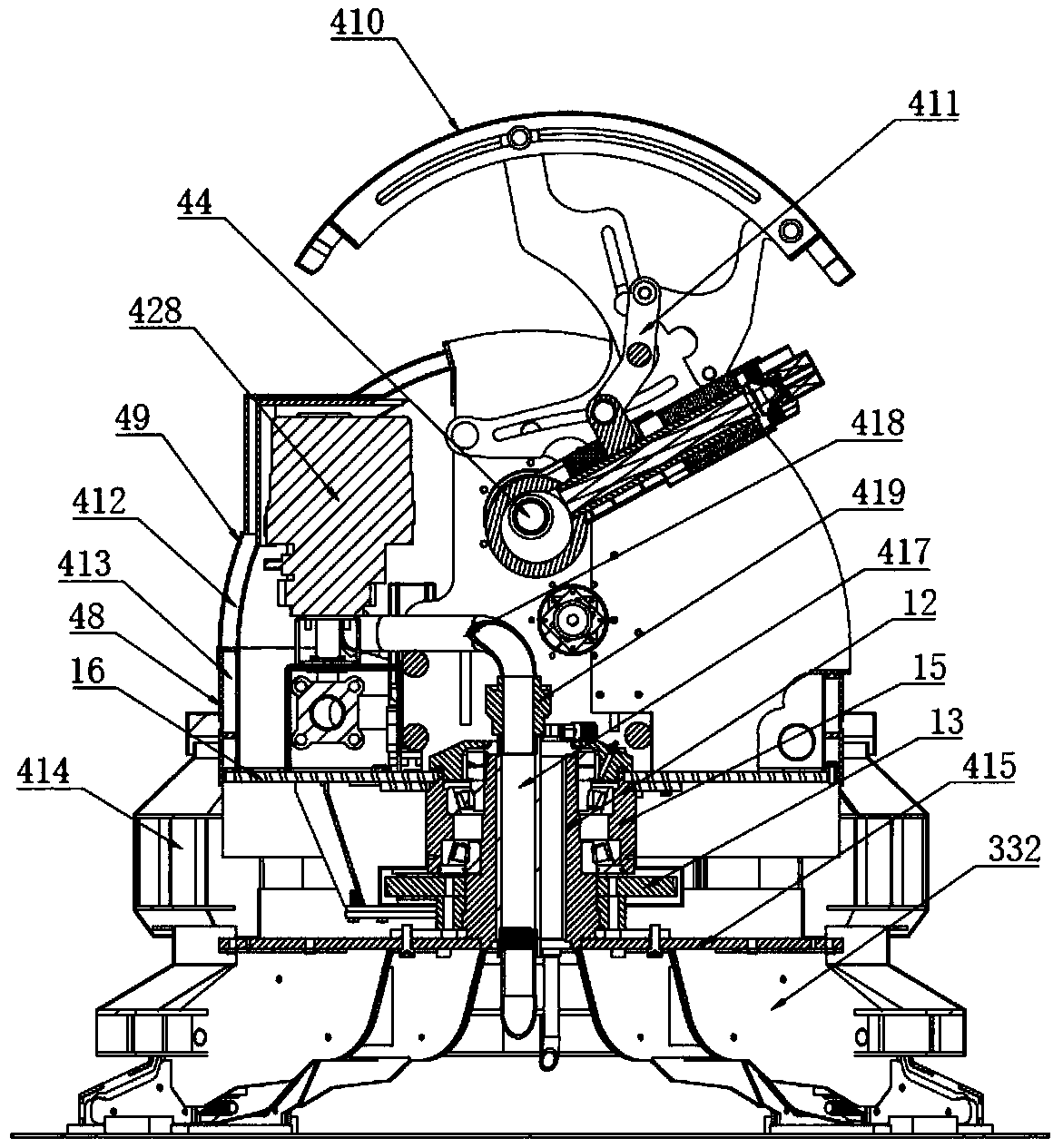
[0188] Embodiment 1: as Figure 1 to Figure 18 As shown, an air purification defense system includes a water supply device and a terminal. The terminal includes a rotary support mechanism, a fluid injection mechanism and a fluid supply pipeline. The rotary support mechanism includes a base 11, a main shaft 12, a main gear 13, and a drive gear 14. Oil cylinder housing 15, rotating platform 16 and gear drive mechanism 17. The main shaft 12 is vertically arranged on the upper surface of the base 11. The main shaft 12 is provided with a main shaft through hole penetrating up and down. The main gear 13 is sleeved and fixed On the outer side of the main shaft 12, the oil cylinder housing 15 is sleeved on the outer side of the main shaft 12 through the main bearing 18, the rotating platform 16 is sleeved and fixed on the oil cylinder housing 15, the driving gear 14 meshes with the main gear 13, and the The gear drive mechanism is arranged on the rotating platform 16, and the gear dri...

Embodiment 2

[0237] Embodiment 2, as a kind of improved scheme of embodiment 1, such as Figure 20 to Figure 22 As shown, the sliding shaft driving mechanism is a hydraulic sliding shaft driving mechanism, and the hydraulic sliding shaft driving mechanism includes a fixed shaft 314, a hydraulic cylinder 316, a coupling 318 and a hydraulic system 317, and the hydraulic system 317 is arranged on the bottom horizontal plate 31, the two ends of the fixed shaft 314 are respectively connected with the two lower support plates 32, the hydraulic system includes an oil storage tank, a hydraulic pump, a one-way valve and a reversing valve, the oil storage tank, hydraulic pump, The one-way valve and the reversing valve are connected in turn through the oil inlet pipeline, the oil storage tank and the reversing valve are connected through the oil return pipeline, the reversing valve and the hydraulic cylinder 316 are connected through two hydraulic pipelines, and the hydraulic cylinder 316 The cylinde...

Embodiment 3

[0240] Embodiment 3, as another kind of improved scheme of embodiment 1, such as Figure 23 and Figure 24 As shown, the sliding shaft driving mechanism is an electric sliding shaft driving mechanism, and the electric sliding shaft driving mechanism includes a leg driving motor controller 321, a leg driving motor 319, a connecting rod 320 and a link 318, and the legs The drive motor 319 is arranged on the bottom horizontal plate 31, the leg drive motor 319 is connected with the leg drive motor controller 321, the leg drive motor 319 is connected with one end of the connecting rod 320, the other end of the connecting rod 320 One end is connected with one end of the coupling part 318 , and the other end of the coupling part 318 is connected with the sliding shaft 35 , and the coupling part 318 is a bolt connecting the sliding shaft 35 and the connecting rod 320 . The terminal controller is connected with the leg drive motor controller 321 through a signal line;

[0241] The ou...


PUM


Abstract

The invention discloses an air purification defense system and belongs to the technical field of environmental protection. The system comprises a water supplying device and a terminal; the terminal comprises a rotating supporting mechanism, a fluid jetting mechanism and a fluid supplying pipeline; the rotating supporting mechanism comprises a base, a main shaft, a main gear, a driving gear, an oilcylinder shell, a rotating platform and a gear driving mechanism; the gear driving mechanism drives the rotating platform to rotate; the fluid jetting mechanism comprises a jetting gun barrel, a gunbarrel supporting frame and a gun barrel driving mechanism; the gun barrel supporting frame is arranged on the rotating platform; the gun barrel driving mechanism is connected with the jetting gun barrel; the fluid supplying pipeline is connected with the jetting gun barrel; the water supplying device is communicated with the fluid supplying pipeline; a high-speed mute pipe intermediate pump is adopted by the water supplying device to provide supercritical fluid for the jetting gun barrel; the jetting gun barrel is wide in covering range, the jetted out fluid is good in atomizing performance and carries lots of negative ions, haze dust in air can be effectively reduced, a purifying effect is achieved on air, and the environment quality is improved.

Description

technical field [0001] The invention belongs to the technical field of environmental protection, in particular to an air purification defense system. Background technique [0002] In recent years, smog has become an environmental problem that plagues most regions in China. For smog control, the emission of exhaust gas can be reduced from the source, such as restricting production at construction sites, restricting the use of cars, and restricting factory emissions. At the same time as emissions, the needs of production and the needs of residents’ lives must also be taken into account. Therefore, the problem of smog is still relatively serious. For the smog that has occurred, people have developed a large number of products to control it, such as the fog cannon vehicles that are often used today. , but the fog cannon vehicle can only control the environment on the road in a small range, and for schools, hospitals, communities and other areas, there are many inconveniences in ...

Claims


Application Information

Patent Timeline
IPC IPC(8): F24F3/14F24F3/16F24F13/00F24F13/32F24F11/89A62C3/02A62C31/00A62C31/28A62C37/00
CPCA62C3/0214A62C31/005A62C31/28A62C37/00F24F3/14F24F3/16F24F13/00F24F13/32F24F8/99F24F8/117F24F8/30
Inventor 顾炎彬
Owner 宙斯流体系统(上海)有限公司
Learn More