
Highway bridge width and height limiting equipment

A technology of highway bridges and grace, applied in bridge construction, bridges, bridge parts, etc., can solve the problems of wasting manpower and material resources, affecting the use of highways, etc., and achieve the effect of convenient processing, improved performance, and convenient use.

Inactive Publication Date: 2018-05-29
ZHENGZHOU GUOZHI NETWORK TECH CO LTD
View PDF6 Cites 5 Cited by
  • Summary
  • Abstract
  • Description
  • Claims
  • Application Information

AI Technical Summary

Problems solved by technology

[0003] In order to better protect the bridge body, the current highway bridges often use width and height limiting equipment to limit vehicles, thereby protecting the bridge. However, the current bridge width and height limiting devices are generally fixed, and there is often no need to carry out emergency measures in case of emergency In this way, only the width and height limit equipment can be disassembled, which not only wastes manpower and material resources, but also affects the use of roads

Method used


Image

  • Highway bridge width and height limiting equipment
  • Highway bridge width and height limiting equipment
  • Highway bridge width and height limiting equipment

Examples


Embodiment Construction

[0018] It should be noted that, in the case of no conflict, the embodiments of the present invention and the features in the embodiments can be combined with each other.

[0019] In describing the present invention, it should be understood that the terms "center", "longitudinal", "transverse", "upper", "lower", "front", "rear", "left", "right", " The orientations or positional relationships indicated by "vertical", "horizontal", "top", "bottom", "inner" and "outer" are based on the orientations or positional relationships shown in the drawings, and are only for the convenience of describing the present invention and Simplified descriptions, rather than indicating or implying that the device or element referred to must have a particular orientation, be constructed and operate in a particular orientation, and thus should not be construed as limiting the invention. In addition, the terms "first", "second", etc. are used for descriptive purposes only, and should not be understood ...


PUM


Abstract

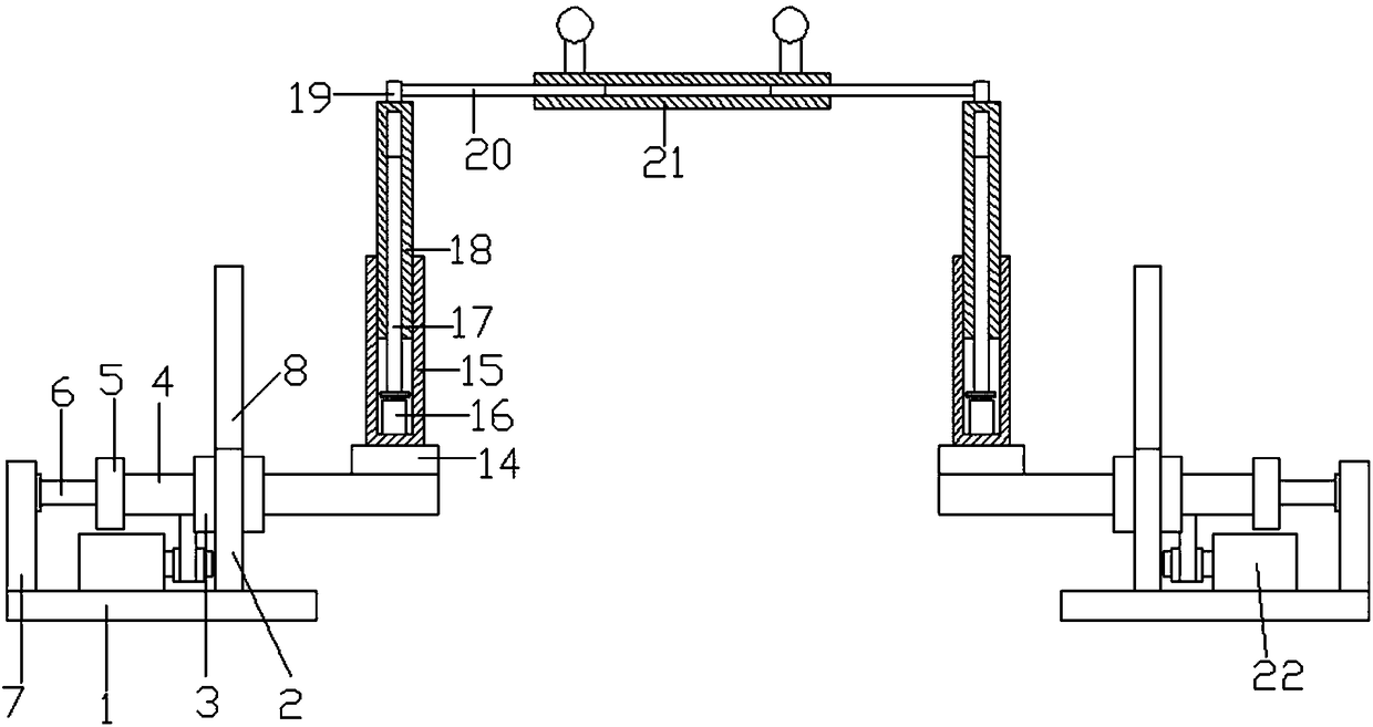
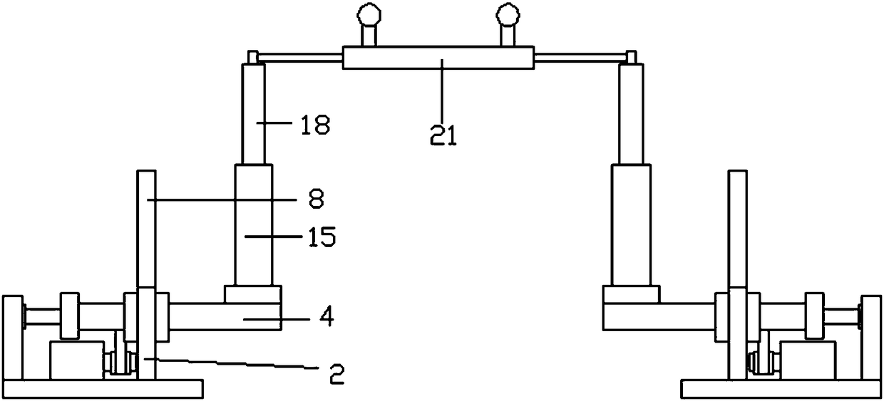
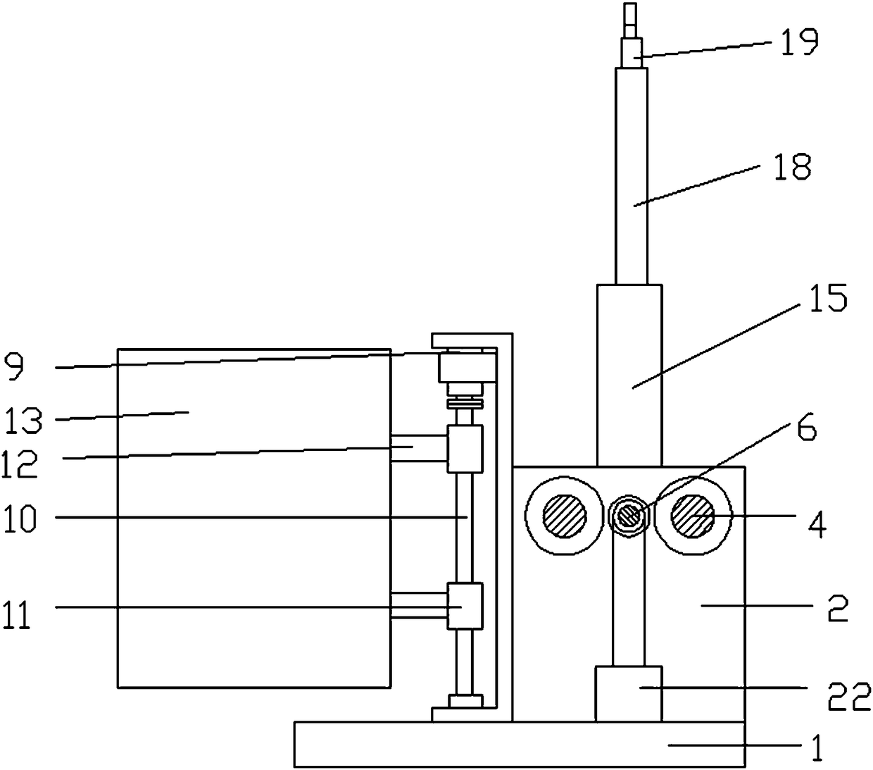
The invention discloses a highway bridge width and height limiting equipment. The highway bridge width and height limiting equipment comprises a bottom plate. The upper side of the bottom plate is provided with a supporting plate. The front side and the back side of the upper end of the supporting plate are provided with connecting sleeves. The interior of each connecting sleeve is provided with afirst connecting rod. The outer side of each first connecting rod is provided with a connecting block. The interior of each connecting block is provided with a first lead screw. The back side of thesupporting plate is provided with a connecting frame. The upper end of the interior of the connecting frame is provided with a second motor. The lower side of the second motor is provided with a rotating shaft. The upper end and the lower end of the rotating shaft are provided with connecting blocks. The back side of each connecting block is provided with a baffle. A connecting plate is arranged at the inner end of the upper side of each first connecting rod. A supporting pipe is arranged on the upper side of each connecting plate. A telescopic rod is arranged on the outer side of the upper end of each supporting pipe. The upper side of each telescopic rod is provided with a mounting seat. The inner side of each mounting seat is provided with a third connecting rod. The middle of each third connecting rod is provided with a connecting pipe. According to the highway bridge width and height limiting equipment, height and width limiting can be effectively conducted on highway bridges, proper height and width adjusting can be conducted in the case of emergent situation, in this way, use of the equipment is facilitated, and the using performance of the equipment is improved.

Description

technical field [0001] The invention relates to the field of highway bridges, in particular to equipment for limiting width and height of highway bridges. Background technique [0002] A bridge (bridge) refers to a building built for roads to cross natural or artificial obstacles. It is erected on rivers, lakes and seas to allow vehicles and pedestrians to pass smoothly. A bridge generally consists of a superstructure, a substructure and ancillary structures. The superstructure mainly refers to the bridge span structure and support system; the substructure includes abutments, piers and foundations; , diversion engineering, etc. According to the structural system of bridges, there are four basic systems: girder bridge, arch bridge, rigid frame bridge, and suspension cable load-bearing (suspension bridge, cable-stayed bridge). [0003] In order to better protect the bridge body, the current highway bridges often use width and height limiting equipment to limit vehicles, ther...

Claims


Application Information

Patent Timeline
Patent Type & Authority Applications(China)
IPC IPC(8): E01D19/00E01F13/00
CPCE01D19/00E01F13/00
Inventor 郜佩环
Owner ZHENGZHOU GUOZHI NETWORK TECH CO LTD
Learn More