
Convection plate structure

A convection plate and bottom-end technology, applied in the field of metallurgy, can solve the problems such as the inability to solve the problems of the outer side of the small coil at the welding seam position, the size and specification, the surface morphology are different, and the effective operation rate of the heat treatment unit is affected, so as to reduce energy consumption and manpower. The effect of waste of resources, improvement of product quality, and improvement of operation rate

Pending Publication Date: 2018-05-29
BENGANG STEEL PLATES
View PDF1 Cites 0 Cited by
  • Summary
  • Abstract
  • Description
  • Claims
  • Application Information

AI Technical Summary

Problems solved by technology

If forced production of wound rolls overflowing from the weld seam will damage the work rolls and form periodic roll marks and marks on the surface of the strip to produce downgraded products
[0007] Fourth, the matching convection plates of different types of German LOI and Austrian EBNER annealing furnaces introduced by the heat treatment unit in different periods are not the same in terms of material selection, size specifications, surface morphology, etc. Interchangeable use affects the effective operating rate of the heat treatment unit
This patent cannot solve the above-mentioned technical problems, especially it cannot solve the p

Method used


Image

  • Convection plate structure
  • Convection plate structure
  • Convection plate structure

Examples


Example Embodiment

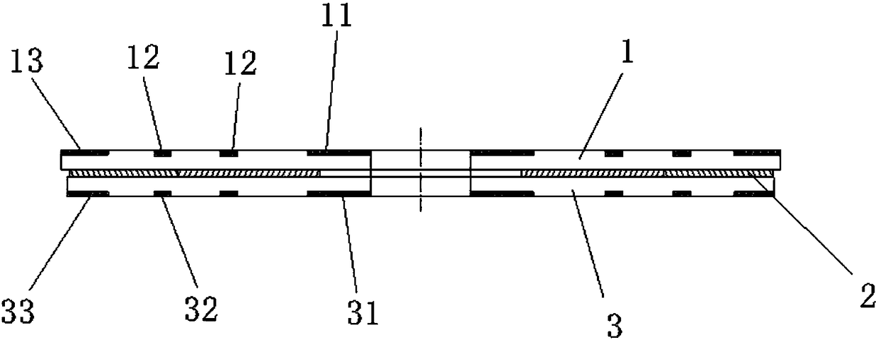
[0017] The present invention will be described in detail below with reference to the drawings, such as figure 1 As shown, the realization process of the technical solution of the present invention is divided into five steps, namely, the optimization of the surface shape of the convection plate, the improvement of the production material, the design of the size specification, the verification of the optimization design effect, and the economic benefits obtained.

[0018] Optimization of convection disk surface morphology

[0019] According to the analysis of the morphological characteristics of the damage caused by the convection plate to the stacked steel coils, the surface morphology of the upper and bottom end plates of the convection plate is redesigned.

[0020] The surfaces of the upper end plate and the bottom end plate of the convection plate are cut. The cutting area is divided into three areas, namely the inner cutting area, the outer cutting area and the middle cutting area...


PUM


Abstract

The invention discloses a convection plate structure. A convection plate is composed of an upper end plate, a middle plate and a bottom end plate from top to bottom. The upper end plate is provided with upper end plate inner side grooves, upper end plate middle grooves and upper end plate outer side grooves from inside to outside. The bottom end plate is provided with bottom end plate inner side grooves, bottom end plate middle grooves and bottom end plate outer side grooves from inside to outside. The upper end plate inner side grooves and the bottom end plate inner side grooves are the samein position and shape. The upper end plate middle grooves and the bottom end plate middle grooves are the same in position and shape. The upper end plate outer side grooves and the bottom end plate outer side grooves are the same in position and depth. The radial length of the upper end plate outer side grooves is larger than that of the bottom end plate outer side grooves. The convection plate structure has the advantages that the specifications of the convection plate are made uniform and reeling damage is reduced on the premise that the heating effect requirement of the steel reel end faceis met and the using intensity of the convection plate is guaranteed.

Description

technical field [0001] The invention relates to the technical field of metallurgy, in particular to a convection plate. Background technique [0002] The bottom convection plate (hereinafter referred to as the convection plate) is one of the auxiliary equipment for cold-rolled bell annealing. Each convection plate is composed of 20 identical fan-shaped sheets. Each sheet consists of an upper end plate, a bottom end plate and a It consists of an intermediate plate between the upper end plate and the bottom end plate. When the bell-type annealing furnace performs recrystallization and bright annealing on the cold-rolled steel coils, the convection plate is placed between the upper and lower stacked steel coils, so that the annealing medium in the inner cover of the annealing furnace can maintain smooth airflow between the stacked steel coils. Improve the heating effect of the end surface of the steel coil, ensure the uniform temperature inside and outside the steel coil durin...

Claims


Application Information

Patent Timeline
IPC IPC(8): C21D9/673
CPCC21D9/673
Inventor 张勇张松岩关立凯
Owner BENGANG STEEL PLATES
Learn More