
Shaft pin assembly machine

A technology of assembly machine and shaft pin, which is applied in metal processing, metal processing equipment, manufacturing tools, etc., can solve the problems of reduced work efficiency, high manufacturing cost, waste of manpower, etc., and achieve the effect of improving production efficiency and reducing use cost

Inactive Publication Date: 2018-05-29
SHIYAN LONGTAIYUAN IND & TRADE
View PDF0 Cites 0 Cited by
  • Summary
  • Abstract
  • Description
  • Claims
  • Application Information

AI Technical Summary

Problems solved by technology

[0005] In order to solve the above technical problems, the present invention provides a shaft pin assembly machine to solve the problem that the existing shaft pin assembly machine needs to be improved due to the large vibration sound caused by the cylinder transmission shaft pin during work, and the manual installation during the assembly process. The shaft pin is easy to be missed, and sometimes the shaft pin will not be installed in place during the installation process, which will not only waste manpower and reduce work efficiency, but also increase the product failure rate, and the assembly size of the shaft pin will also increase during assembly. There are differences, which will increase the reject rate of the product, and the tire molds of the existing shaft pin assembly machines are all fixed installations, so that one device can only assemble one type of shaft, and the manufacturing cost used is relatively low. high problem

Method used


Image

  • Shaft pin assembly machine
  • Shaft pin assembly machine
  • Shaft pin assembly machine

Examples


Embodiment

[0023] as attached figure 1 to attach Figure 5 Shown:

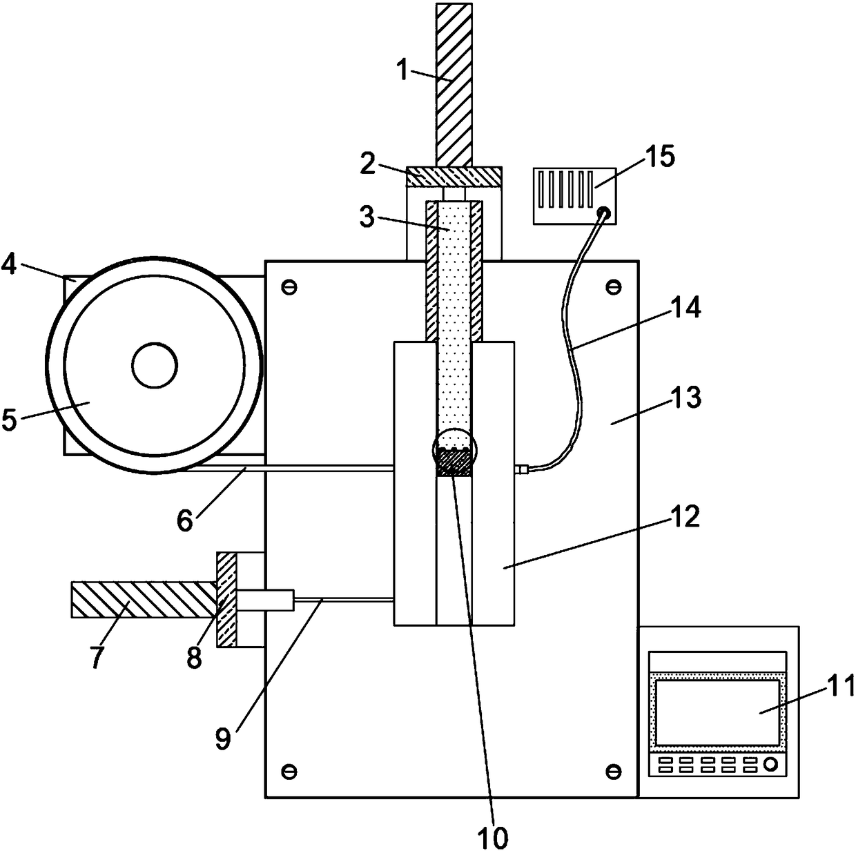
[0024] The invention provides a shaft pin assembly machine, which includes No. 1 cylinder 1, No. 1 cylinder fixing seat 2, push plate 3, vibration plate support plate 4, vibration plate 5, shaft pin transmission pipe 6, No. 2 cylinder 7, No. 2 Cylinder holder 8, top tight rod 9, fixed tire mold 10, console 11, processing table 12, support table 13, pressure pipe 14 and suction pump 15; the top of support table 13 is fixedly provided with a processing table 12; The inner side of the processing table 12 is movably embedded with a push plate 3; one side of the push plate 3 is embedded with a fixed tire template 10; one side of the support table 13 is fixedly installed with a second cylinder 7 through the second cylinder fixing seat 8 One side of the No. 2 cylinder 7 is fixedly provided with a tightening thin rod 9, and the other side of the tightening thin rod 9 is movably embedded in one side of the processing table 12; ...


PUM


Abstract

The invention provides a shaft pin assembly machine. The shaft pin assembly machine comprises a pushing plate, a jacking fine rod and a fixed tire mould, wherein the inner part of a processing table board is movably embedded with a pushing plate; and one side of the pushing plate is embedded with a fixed tire molding board. The fixed tire mould is arranged, so that using cost is favorably reduced;when the device is used, the fixed tire mould which corresponds to a processed rotary shaft can be firstly selected, the pushing plate is pushed by an air cylinder I to outwards push out towards oneside of the processing table board, the to-be-used fixed tire mould is embedded into a groove in one side of the pushing plate through a T-shaped bulge, and the bottom bulge of the fixed tire mould isembedded into the groove in the bottom of the pushing plate, so that the fixed tire mould can be fixed; when different rotary shafts need to assemble, the corresponding fixed tire mould can be firstly mounted at one side of the pushing plate and then is assembled; and rotary shafts of various specifications can be assembled by manufacturing a plurality of fixed tire moulds, so that use cost is effectively reduced.

Description

technical field [0001] The invention belongs to the technical field of mechanical processing devices, in particular to a shaft pin assembly machine. Background technique [0002] The pin is assembled on the shaft to fix some workpieces. The traditional pin assembly is usually manually assembled with the pin on the shaft. Since the pin and the shaft are generally tight fit, when assembling It needs manpower and cannot realize the automation of pin shaft assembly, which affects the efficiency of pin shaft assembly, so some shaft pin assembly equipment has appeared now. [0003] Based on the above, the inventors found that the existing shaft pin assembly machine needs to be improved due to the large vibration sound caused by the transmission of the shaft pin by the cylinder during work, and the manual installation of the shaft pin during the assembly process is easy to miss. During the process, sometimes the shaft pins will not be installed in place, which will not only waste ...

Claims


Application Information

Patent Timeline
Patent Type & Authority Applications(China)
IPC IPC(8): B23P19/00B23P19/027
CPCB23P19/001B23P19/027
Inventor 刘文巴志强
Owner SHIYAN LONGTAIYUAN IND & TRADE
Learn More