Self-propelled miniature rotary cultivator

A self-propelled, rotary tiller technology, applied in the fields of farming equipment, agricultural machinery and equipment, and applications, can solve the problems of poor turning maneuverability and aggravate the loss of parts, and achieve convenient hydraulic control, improved work efficiency, and stable power. Effect

Inactive Publication Date: 2018-05-29
NANJING ZHIQIAO AGRI CO LTD
View PDF5 Cites 4 Cited by
  • Summary
  • Abstract
  • Description
  • Claims
  • Application Information

AI Technical Summary

Problems solved by technology

[0002] At present, with the continuous development of science and technology and the continuous progress of society, all walks of life are developing rapidly at different speeds. As a large agricultural country, my country attaches great importance to the development of agriculture. From the previous manual work to mechanized labor, The development of machines has played a non-negligible role in the development of the industry and the improvement of work efficiency; as different soil tillage machines, the structures and properties of their working parts are different, and the commonly used mechanical transmissions are mostly hard transmissions. When encountering complex soil conditions, if the environment is poor, long-term cultivation will greatly increase the loss of parts. At the same time, after completing a job, the turning maneuverability is poor, so we need a self-propelled small rotary tiller

Method used


Image

  • Self-propelled miniature rotary cultivator
  • Self-propelled miniature rotary cultivator
  • Self-propelled miniature rotary cultivator

Examples


Embodiment Construction

[0024] The present invention will be further described in detail below in conjunction with the accompanying drawings, so that those skilled in the art can implement it with reference to the description.

[0025] It should be understood that terms such as "having", "comprising" and "including" used herein do not exclude the presence or addition of one or more other elements or combinations thereof.

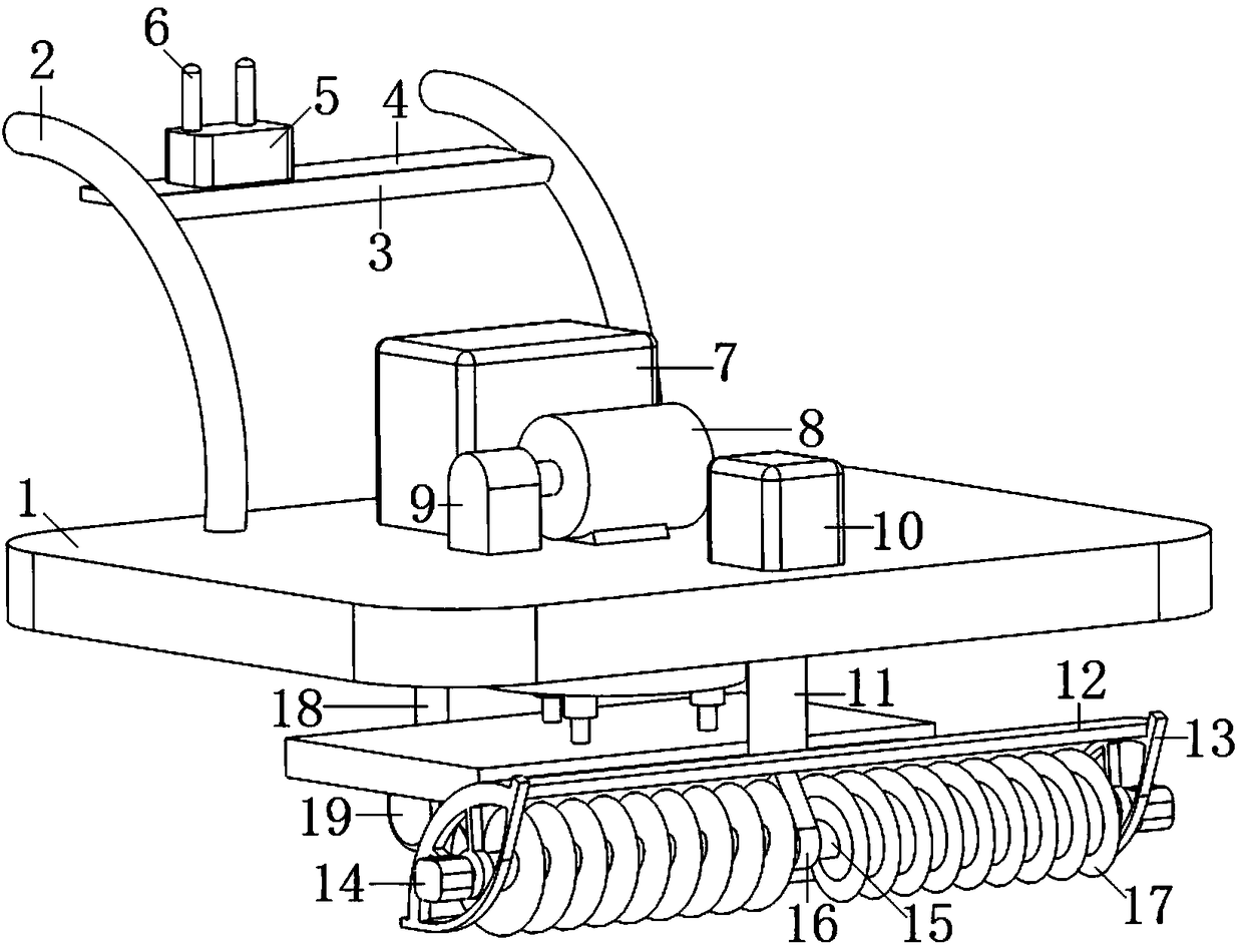
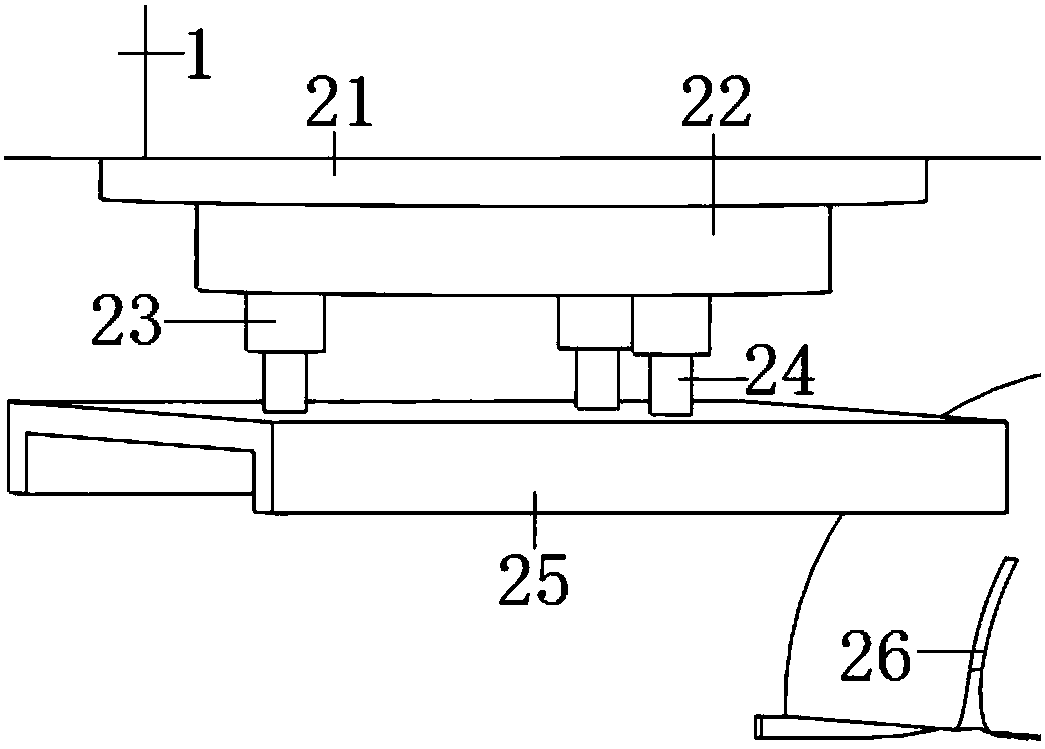
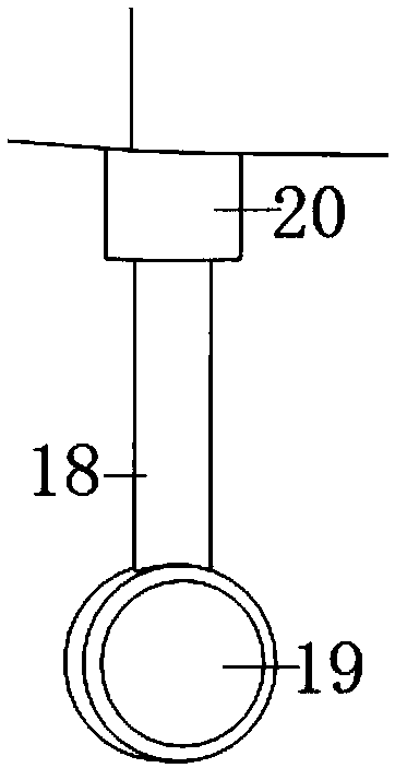
[0026] Such as Figure 1-5 As shown, the present invention provides a kind of self-propelled small-sized rotary tiller, comprising:

[0027] The hydraulic power device is provided with a main board 1 in the middle of the whole device, and the main board 1 is a rectangular metal plate. Two handles 2 are provided on the rear side of the upper surface of the main board 1, and a connecting rod 3 is provided in the middle of the two handles 2. The rear side of the connecting rod 3 is provided with a support plate 4, the upper side of the support plate 4 is provided with a hydraulic val...


PUM


Abstract

The invention discloses a self-propelled miniature rotary cultivator. A main plate is arranged in the middle of the whole device, two handles are arranged on the rear side of the upper surface of themain plate, a connecting rod is arranged at the middle sections of the two handles, a supporting plate is arranged on the rear side of the connecting rod, a hydraulic valve is arranged on the upper side of the supporting plate, rocking bars are arranged at the top of the hydraulic valve, an oil tank is arranged in the middle of the upper side of the main plate, an engine is arranged on the front side of the oil tank, and a hydraulic pump is arranged on the left side of the engine; a fixing base is arranged on the front side of the engine, a connection shaft is arranged at the bottom of the fixing base, a baffle is arranged at the bottom of the connection shaft, an unloading groove is formed in the bottom end of the baffle, side plates are arranged on both sides of the baffle, hydraulic motors are arranged on the outer sides of the side plates, a connecting shaft is arranged in the baffle, and a connecting plate is arranged in the middle of the connecting shaft; a rotary base is arranged at the bottom of the main plate, a rotary disc is arranged at the bottom of the rotary base, three hydraulic cylinders are arranged at the bottom of the rotary disc, hydraulic rods are arranged at the bottoms of the hydraulic cylinders, and a soil grouser is arranged at the bottoms of the hydraulic rods. The self-propelled miniature rotary cultivator is convenient to move, stable in power outputand high in working efficiency.

Description

technical field [0001] The invention relates to the field of agricultural machinery, more specifically, the invention relates to a self-propelled small rotary tiller. Background technique [0002] At present, with the continuous development of science and technology and the continuous progress of society, all walks of life are developing rapidly at different speeds. As a large agricultural country, my country attaches great importance to the development of agriculture. From the previous manual work to mechanized labor, The development of machines has played a non-negligible role in the development of the industry and the improvement of work efficiency; as different soil tillage machines, the structures and properties of their working parts are different, and the commonly used mechanical transmissions are mostly hard transmissions. When encountering complex soil conditions, if the environment is poor, long-term cultivation will greatly increase the loss of parts. At the same ti...

Claims


Application Information

Patent Timeline
Patent Type & Authority Applications(China)
IPC IPC(8): A01B33/02A01B33/08
CPCA01B33/022A01B33/082
Inventor 莫文油韦瑞克
Owner NANJING ZHIQIAO AGRI CO LTD
Why Eureka
Try Eureka