EGR pipe and EGR system

A pipe and tee pipe technology, applied in the field of EGR pipe and EGR system, can solve the problems of high EGR rate and difficulty in reaching the EGR system of the engine exhaust pipeline, and achieve the solution of EGR rate, rapid position switching, and guaranteed sealing Effect

Active Publication Date: 2018-05-25
WEICHAI POWER CO LTD
View PDF7 Cites 8 Cited by
  • Summary
  • Abstract
  • Description
  • Claims
  • Application Information

AI Technical Summary

Problems solved by technology

[0006] The purpose of the present invention is to provide an EGR pipe and an EGR system to solve the problem that the EGR system of the existing engine exhaust pipeline is difficult to achieve a higher EGR rate

Method used


Image

  • EGR pipe and EGR system
  • EGR pipe and EGR system
  • EGR pipe and EGR system

Examples


Embodiment Construction

[0031] The technical solutions of the present invention are further described below with reference to the accompanying drawings and through specific embodiments.

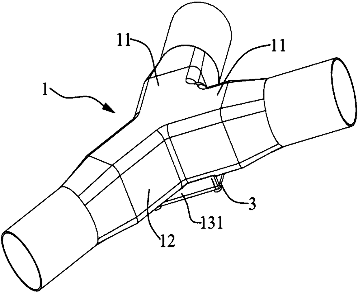
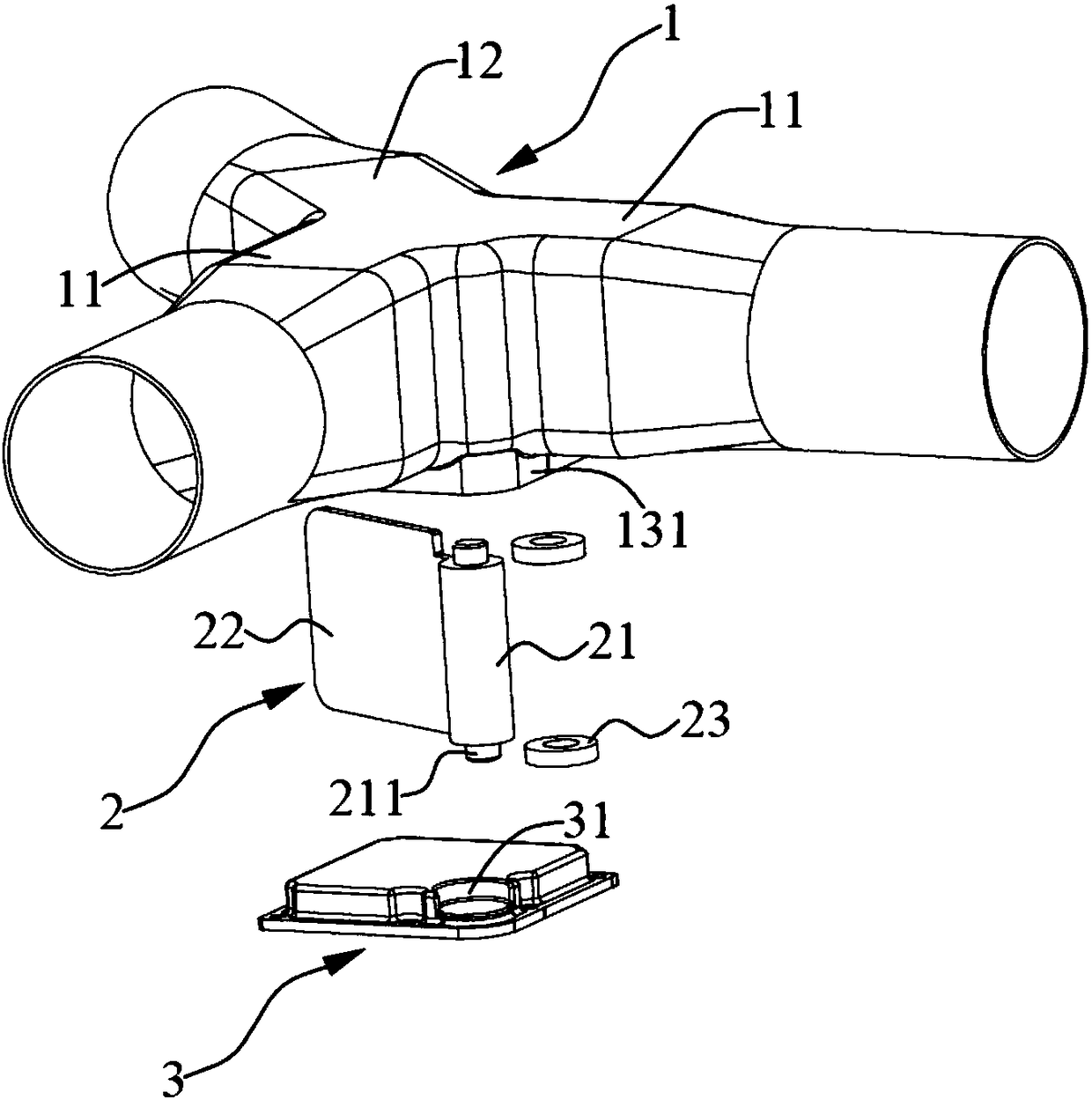
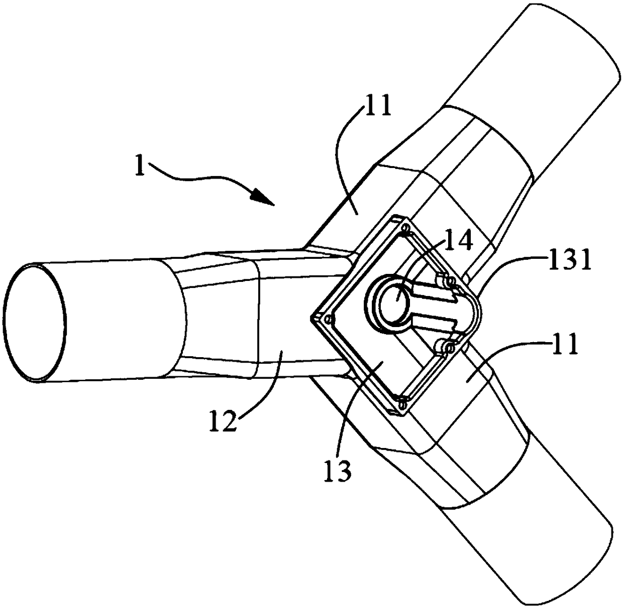
[0032] like Figure 1 to Figure 4 As shown, this embodiment provides an EGR pipe, including a three-way pipe 1 and a switching valve 2 arranged at the intersection of the three-way pipe 1. The three-way pipe 1 includes two exhaust gas intake branches 11 and two The exhaust gas intake trunk 12 connected to the exhaust gas intake branch 11, the intersection of the three-way pipe 1 pipeline is the intersection of the two exhaust gas intake branches 11 pipelines, the switching valve 2 includes a paddle 22, a paddle 22 One end is provided with a rotating shaft 21, and the rotating shaft 21 is rotatably arranged at the intersection of the pipes of the tee pipe 1, that is, the intersection of the two exhaust gas intake branches 11. The cross-sectional shape is the same. The switching valve 2 is arranged at the intersecti...


PUM


Abstract

The invention discloses an EGR pipe and an EGR system, and relates to the technical field of engines. The EGR pipe comprises a three-way pipe and a switching valve internally arranged at the pipe intersection position of the three-way pipe, the switching valve comprises a pulling sheet, one end of the pulling sheet is provided with a rotating shaft, the rotating shaft is rotationally arranged at the intersection position of two gas inlet branches, the shape of the pulling sheet is the same as the shape of the cross section of a pipe body of the three-way pipe. According to the EGR pipe, in themanners that the switching valve is arranged at the pipe intersection position of the three-way pipe and the shape of the pulling sheet is the same as the shape of the cross section of the three-waypipe, the switching valve can achieve free rotation through the two waste gas inlet branches, free switching of the switching valve at the positions of the waste gas inlet branches is achieved, and the condition of waste gas backflow of the two waste gas inlet branches is avoided, and the problem that an existing engine exhaust pipe EGR system cannot obtain the high EGR efficiency is solved.

Description

technical field [0001] The invention relates to the technical field of engines, in particular to an EGR pipe and an EGR system. Background technique [0002] Automobile engines usually adopt the Exhaust Gas Recirculation (EGR) method. EGR is a technology in which a part of the exhaust gas is separated from the internal combustion engine after combustion and introduced into the intake side for re-combustion, which is conducive to reducing the amount of exhaust gas in the exhaust gas. Nitrogen oxides (NO X ) and particulates, while increasing fuel consumption while sharing part of the load, further improving fuel economy. [0003] Due to the inherent characteristics of the engine and the supercharger, when the engine is in the low-speed and high-torque region, the intake pressure after the intercooling is often higher than the vortex front pressure of the supercharger, so it is difficult to achieve EGR. Due to the existence of the engine exhaust pulse, the peak pressure of t...

Claims


Application Information

Patent Timeline
Patent Type & Authority Applications(China)
IPC IPC(8): F02M26/14F02M26/16
CPCF02M26/14F02M26/16
Inventor 李卫刘俊龙李志杰潘洁刘春涛王作峰康天钦
Owner WEICHAI POWER CO LTD
Why Eureka
Try Eureka