Elevator cable inspection system

A technology for inspection systems and steel cables, which can be used in transportation and packaging, elevators, etc., and can solve the problems of complex structure of steel cables and rising manufacturing costs.

Active Publication Date: 2019-09-03
TOSHIBA ELEVATOR KK
View PDF8 Cites 0 Cited by
  • Summary
  • Abstract
  • Description
  • Claims
  • Application Information

AI Technical Summary

Problems solved by technology

However, the former method is limited to steel cable structures with less single wires such as steel wires.
Although the latter method can be applied to steel cables with aramid fiber and resin coating, the structure of the steel cable becomes complicated, which leads to an increase in manufacturing costs

Method used


Image

  • Elevator cable inspection system
  • Elevator cable inspection system
  • Elevator cable inspection system

Examples


no. 1 Embodiment approach

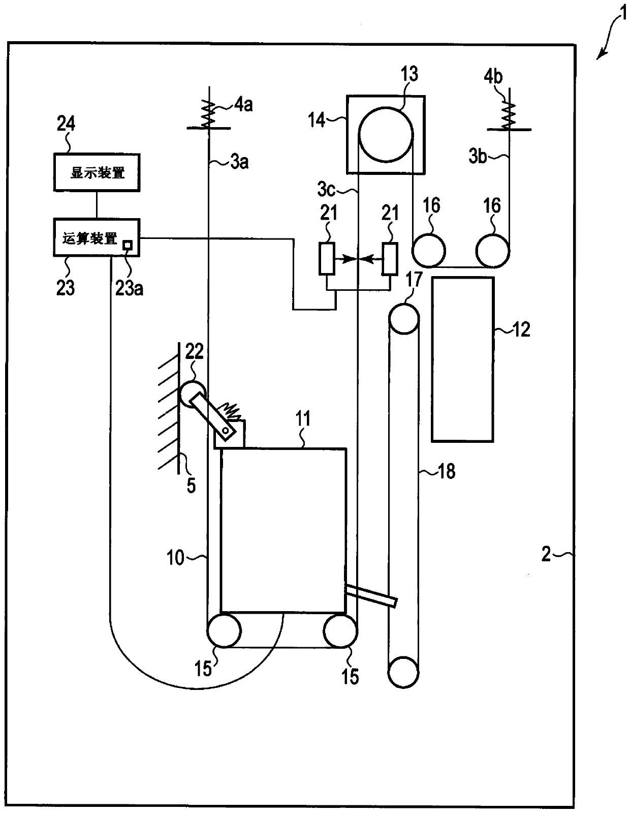
[0023] figure 1 It is a figure showing the schematic structure of the machine-room-less elevator of 1st Embodiment.

[0024] The elevator 1 has a hoistway 2 installed in a building, and a car 11 and a counterweight 12 are supported inside the hoistway 2 so as to be movable up and down via guide rails. Furthermore, a hoist 14 having a traction sheave 13 is installed on the upper portion of the hoistway 2 .

[0025] The car 11 and the counterweight 12 are suspended in the hoistway 2 via a plurality of main steel cables 10 . Furthermore, figure 1 Only one main steel cable 10 is shown in the figure, and the illustration of other main steel cables 10 is omitted.

[0026] The one end 3a and the other end 3b of the main wire rope 10 are fixed to the upper end of the hoistway 2 via rope locks 4a, 4b, respectively. In addition, the intermediate portion 3 c of the main wire rope 10 is continuously wound around a pulley 15 provided on the car 11 , a traction sheave 13 provided on the...

no. 2 Embodiment approach

[0080] Next, a second embodiment will be described.

[0081] In the above-mentioned first embodiment, the encoder 22 is provided on the car 11, and the pulse signal output from the encoder 22 is counted. A rotary encoder is used as the encoder 22, but a linear encoder (not shown) that magnetically or optically outputs pulses in the hoistway 2 along the ascending and descending direction of the car 11 may also be used.

[0082] Here, as the pulse generating unit, as long as it has a structure that generates a pulse signal substantially synchronously with the feeding amount of the main steel cable 10, that is, as long as it generates a pulse signal as the car 11 and the counterweight 12 move up and down. structure, the effect is the same. Therefore, the existing encoder installed in the elevator 1 for detecting the car position and speed can be used.

[0083] Next, the configuration in the case where an existing encoder is used as the pulse generator of this system will be des...


PUM


Abstract

An object of the present invention is to measure the marking interval during inspection without placing a burden on maintenance personnel, and to determine the deterioration state based on the marking interval. An elevator wire rope inspection system according to an embodiment of the present invention includes a sensor (21), an encoder (22), and a computing device (23). A sensor (21) detects a plurality of marks provided at regular intervals along the length direction of a main steel cable (10) to be inspected. The encoder (22) generates a pulse signal synchronously with the movement of the main cable (10). The calculation device (23) calculates the interval of each mark according to the detection time of each mark obtained by the sensor (21) and the count value of the pulse signal output from the encoder (22), and determines the main steel cable according to the calculation result. (10) Deterioration state.

Description

[0001] This application is based on Japanese Patent Application No. 2016-218677 (application date: 11 / 9 / 2016), and enjoys priority based on this application. This application incorporates this application in its entirety by reference. technical field [0002] An embodiment of the present invention relates to a wire rope inspection system for inspecting a state of deterioration of wire ropes used for, for example, a main wire rope of an elevator. Background technique [0003] In recent years, steel cables in which the surface of a tensile member is covered with a resin material such as polyurethane, which has abrasion resistance and a high coefficient of friction, have spread widely. Such a wire rope cannot visually observe the internal tensile member, and therefore cannot perform strength management by visual inspection of the wear state of a single wire and the number of broken wires. Therefore, for example, a method of applying current to a single wire and measuring chang...

Claims


Application Information

Patent Timeline
Patent Type & Authority Patents(China)
IPC IPC(8): B66B7/12B66B5/00
CPCB66B5/0025B66B7/1238
Inventor 长田朗高泽理志
Owner TOSHIBA ELEVATOR KK
Why Eureka
Try Eureka