
Automatic gain control circuit and signal processing system

An automatic gain control and circuit technology, applied in the direction of gain control, amplification control, electrical components, etc., can solve the problems of counting error, output signal deviation, large release rate error, etc., to meet the requirements of high precision and increase precision , to avoid the effect of timing error

Active Publication Date: 2018-05-22
SHANGHAI AWINIC TECH CO LTD
View PDF7 Cites 2 Cited by
  • Summary
  • Abstract
  • Description
  • Claims
  • Application Information

AI Technical Summary

Problems solved by technology

[0006] In order to solve the above-mentioned technical problems, the present invention provides an automatic gain control circuit and a signal processing system to solve the problem that the actual compression rate or the actual release rate is different from the preset compression rate or release rate due to the switching of the clock signal. Large, resulting in the deviation of the output signal, and when the signal to be processed by the automatic gain control circuit is closer to the set release threshold or compression threshold, it will cause serious counting errors

Method used


Image

  • Automatic gain control circuit and signal processing system
  • Automatic gain control circuit and signal processing system
  • Automatic gain control circuit and signal processing system

Examples


Embodiment Construction

[0034] As described in the background, there are two main problems in the automatic gain control circuit in the prior art:

[0035] (1) When setting a small compression rate or release rate, the actual compression rate or actual release rate will increase rapidly as the frequency of the signal to be processed increases:

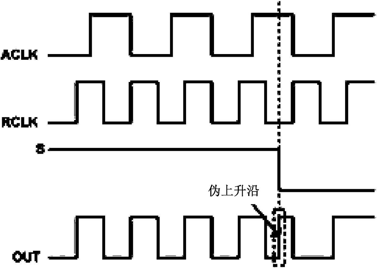
[0036] Specifically, refer to figure 2 , figure 2 is a schematic structural diagram of a typical clock selection circuit in the prior art, in figure 2 It can be seen from the figure that the clock selection circuit is mainly composed of one NOT gate NOR and three NAND gates NAND, where ACLK represents the clock signal used by the reversible counter in the accumulative state, and RCLK represents the clock signal used by the reversible counter in the accumulative state. The clock signal, S represents the clock selection signal; when the reversible counter changes from the accumulative state to the accumulative state (that is, from the release rate to the c...


PUM


Abstract

The invention discloses an automatic gain control circuit and a signal processing system, wherein the clock module of the automatic gain control circuit provides only one working clock to a reversiblecounter; in comparison with the use of the multi-clock to realize the adjustment of the gain change rate, the automatic gain control circuit realizes the adjustment of the gain change rate by changing the number of the counting units participating in counting in the reversible counter, so that the problem that the error between an actual compression rate or an actual release rate and a preset compression rate or a release rate is large, which is caused by switching of the clock signals in the multi-clock system, is solved, and the problem that the output signal of the reversible counter causes deviation is avoided. Further, a clock signal with a higher frequency can be selected as a working clock in practical application so as to avoid the timing error occurring when the signal to be processed is closer to a set compression threshold value, so that the requirements of application scenes with high precision requirements can be met.

Description

technical field [0001] The present application relates to the technical field of automatic control, and more specifically, relates to an automatic gain control circuit and a signal processing system. Background technique [0002] Automatic Gain Control (AGC) is a technical means widely used in the field of signal processing. In particular, in audio power amplifiers, in order to improve the effect of music playback and increase the loudness of music playback, the current audio power Most amplifiers have a complex automatic gain control circuit, and the function of the automatic gain control circuit is similar to the compression function or limiting function in sound processing. As the input signal increases, the output power increases accordingly. After the output power exceeds the set startup threshold, this function will actively reduce the internal gain of the power amplifier to limit the output power below the set threshold; when the input signal Decrease, after the outp...

Claims


Application Information

Patent Timeline
IPC IPC(8): H03G3/30
CPCH03G3/3005
Inventor 陆自清薛蓉何均张海军管少钧
Owner SHANGHAI AWINIC TECH CO LTD
Learn More