
Bidirectional locking manual knife

A manual knife and one-way locking technology, applied in the field of manual knife, can solve the problems of hand injury and hidden dangers

Inactive Publication Date: 2018-05-22
HANGZHOU GREAT STAR IND CO LTD +1
View PDF0 Cites 0 Cited by
  • Summary
  • Abstract
  • Description
  • Claims
  • Application Information

AI Technical Summary

Problems solved by technology

[0003] The technical problem to be solved and the technical task proposed by the present invention are to overcome the defect of the hidden danger of hand injury when the existing foldable knives are folded, and to provide a two-way locking manual knife

Method used


Image

  • Bidirectional locking manual knife
  • Bidirectional locking manual knife
  • Bidirectional locking manual knife

Examples


Embodiment Construction

[0043] The present invention will be further described below in conjunction with the accompanying drawings of the description.

[0044] Figure 1-10B It is a preferred embodiment of the present invention, which expresses the concept of the present invention in detail.

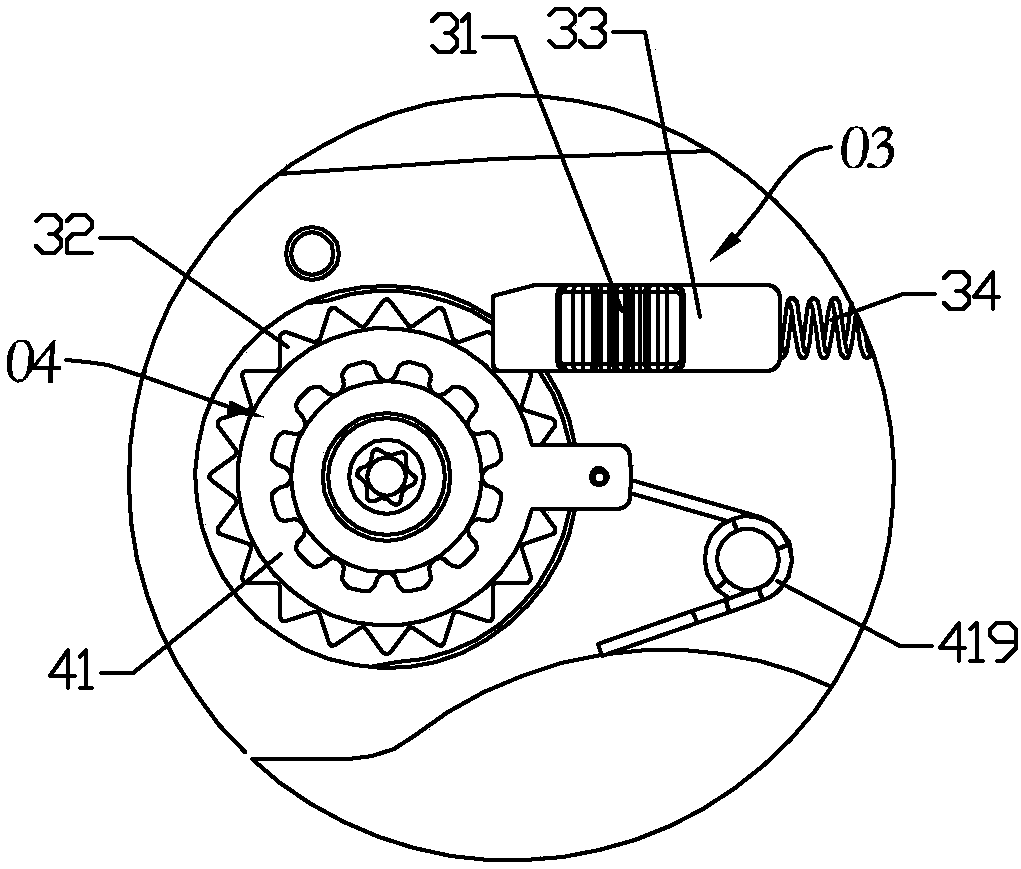
[0045] like Figure 1-2 , Figure 5As shown, the two-way locking manual knife includes a handle 01 and a turning part 02 that is rotatably assembled on the handle. The turning part shown in the figure is a knife holder equipped with a replaceable blade. The part can also be a cutting knife, and the turning part 02 is equipped with a first one-way locking mechanism 03 and a second one-way locking mechanism 04 respectively used to prevent the turning part from unfolding and collapsing. The first one-way locking mechanism 03 has a second one-way locking mechanism. An unlocking operation part 31 is used for releasing the blocking of the first one-way locking mechanism, and the second one-way locking mechanism 04...


PUM


Abstract

The invention discloses a bidirectional locking manual knife, and belongs to a manual tool. When an existing foldable cutter is folded, hidden danger of hurting a hand exists. The manual knife comprises a knife handle, a turning portion rotatably assembled on the knife handle, and a first one-way locking mechanism and a second one-way locking mechanism respectively configured for the turning portion and used for stopping the turning portion to unfold and fold. The first one-way locking mechanism has a first unlocking handle portion, used to relieve stopping of the first one-way locking mechanism. The second one-way locking mechanism has a second unlocking handle portion used to relieve stopping of the second one-way locking mechanism. Therefore, when the manual knife is used, the turning portion can be locked on any part between folding and completely unfolding through the first one-way locking mechanism and the second one-way locking mechanism. When the turning portion needs rotating,stopping of the first one-way locking mechanism or stopping of the second one-way locking mechanism is relieved, and the turning portion can rotate to the corresponding direction.

Description

technical field [0001] The invention belongs to manual tools, in particular to a manual knife capable of bidirectionally locking the turning part of the knife. Background technique [0002] There are various kinds of foldable knives. Most of the knives lock the blade or the cutter head by the cooperation of the back of the blade or the cutter head and the locking structure. The most common locking structure is the back of the knife handle. Hook connecting rod locking structure, the head of the knife is hinged on the handle by turning and pulling, and there is a groove on the back of the knife at the end of the heel, the middle part of the connecting rod is hinged on the back of the handle, and the rear end of the connecting rod is pressed on the handle On the spring in the back, under the upward action of the elastic force, the hook at the front end of the connecting rod is inserted into the groove on the back of the knife; at this time, the knife head is in the open and upr...

Claims


Application Information

Patent Timeline
IPC IPC(8): B26B1/04
CPCB26B1/046B26B1/048
Inventor 王伟毅蒋杭伟
Owner HANGZHOU GREAT STAR IND CO LTD
Learn More