Walking type mower

A lawn mower, walking technology, applied in the direction of harvesters, cutters, agricultural machinery and implements, etc., can solve the problems of hindering the lawn mower to advance by hand, slow cutting speed of nylon rope, and scattering of small stones and other debris.

Active Publication Date: 2018-05-22
YITIANJI POWER MACHINERY RES DEV LINYI
View PDF7 Cites 4 Cited by
  • Summary
  • Abstract
  • Description
  • Claims
  • Application Information

AI Technical Summary

Problems solved by technology

[0004] And there are following shortcoming in the prior art: 1. the position of cutting weeds of nylon rope cutting tool is close to the rotation center, the cutting speed of nylon rope is slow, and the phenomenon of entanglement of grass can occur; It will touch the ground, and there will be resistance between it and the ground, which will consume energy and hinder the hand push of the lawn mower; 3. When the rotating cutter touches the ground, there will be a danger of flying debris such as small stones

Method used


Image

  • Walking type mower
  • Walking type mower
  • Walking type mower

Examples


Embodiment 1

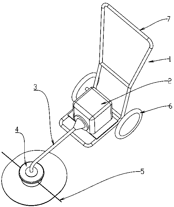
[0024] Such as Figure 1 to Figure 3 As shown, there is a lawn mower with a structure that transmits the rotational power generated by the engine and the motor to the rotary cutter equipped on the front end of the operating rod. The lawn mower is mounted on a frame with wheels and handles, and the operator walks and pushes Use the handle to move the mower along the ground for the desired mowing. One end of the frame 1 is provided with a power source 2 such as an engine or a motor, and the drive member inserted in the drive tube 3 rotates to transmit power to the front end of the drive tube 3 . The frame 1 is grouped with wheels 6, 7 that can freely rotate relative to the frame, and is a handle portion that constitutes a part of the frame.

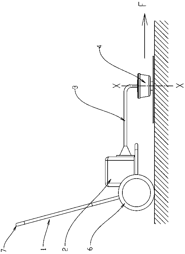
[0025] On the front end of the drive pipe 3, the rotational power of the engine is transmitted to the nylon rope holding member 4, and the nylon rope holding member 4 rotates around the rotation axis X-X. The nylon string cutting blade 5 ...

Embodiment 2

[0028] In order to reduce the resistance between the weeds and the grounding member when the mower advances and mows, and prevent the weeds from lodging, the outer edge of the grounding member 14 is provided with a ring-shaped flange 17, Figure 5 In the above embodiment, the flange 17 is arranged as a raised ring structure on the top surface opposite to the ground surface of the guide member.

[0029] Such as image 3 As shown, the rotation diameter L of the front end portion of the nylon cord cutting tool 5 is larger than the axial width B of the wheel. Therefore, there will be no residue left over from cutting while mowing forward.

Embodiment 3

[0031] In this embodiment, the shape of the outer edge of the ground member 14 is not limited to a standard circle centered on the rotation axis X-X. For example in Figure 4 In the embodiment, with respect to the plane P-P including the rotation axis X-X, the area of ​​one side of the ground member is larger than the area of ​​the other side. A plurality of crowbars 16 are arranged symmetrically with respect to the plane P-P on the grounding surface of the grounding member, and the length of the crowbar is longer on the side of the larger area of ​​the grounding member than on the side of the smaller area relative to the plane P-P. By the setting of the sled bar 16, when the lawn mower advances, the contact area between the ground plate and the ground is small, and the forward resistance becomes smaller.

[0032] In addition, with respect to the plane P-P, through the grounding parts with different grounding areas and the sled bars 16 with different lengths, when the lawn mo...


PUM


Abstract

The invention relates to a mowing device and provides a walking type mower. The walking type mower includes a rack for supporting, and a cutting tool is arranged on the rack; the cutting tool includesa holding member which rotates with a cutting tool mounting shaft as a center, a rope shaped cutting tool body held by the holding member, and a grounding member which rotates with a rotating shaft as a center relative to the holding member; the grounding member which rotates with the mounting shaft as a center relative to the holding member is arranged below the holding member, and a guide partwhich coincides with the traveling direction is arranged on the ground side of the grounding member. The walking type mower is provided with the grounding member capable of maintaining a stationary state when the walking type mower is in contact with the ground. Frictional resistance between the nylon rope holding member and the ground is reduced by means of a pinch bar on the grounding member when walking type mower moves forward to cut grass, and the walking type mower is easier to operate and moves in the desired direction.

Description

technical field [0001] The present application relates to a lawn mower, in particular to a walking lawn mower. Background technique [0002] As a machine to remove weeds growing in the field, the hand push lawn mower includes a rotary cutter equipped with an engine or motor for generating rotational power, and the front end of the operating rod. The lawn mower is mounted on a frame with wheels and a handle On the machine, the operator walks and pushes the handle to move the mower along the ground to perform the desired mowing operation. Figure 6 and Figure 7 is an example of such a lawnmower configuration. Wherein, 1 is a frame, and power sources such as an engine and a motor are fixed on the frame 1. The drive tube 3 connected to the power source 2 extends, and the drive tube 3 has a built-in rotating member that transmits the power generated by the power source 2 to the outside. The front end of the driving tube 3 is connected with a rotating tool holding member 4 and...

Claims


Application Information

Patent Timeline
Patent Type & Authority Applications(China)
IPC IPC(8): A01D34/416
CPCA01D34/416
Inventor 栗原克己久我敏德
Owner YITIANJI POWER MACHINERY RES DEV LINYI
Why Eureka
Try Eureka