Flight control shock absorption device and unmanned aerial vehicle

A shock-absorbing device and flight control technology, applied in shock absorbers, aircraft parts, springs/shock absorbers, etc., can solve problems such as drone execution deviation, flight control system impact, crashes, etc., to absorb impact kinetic energy , Safe and reliable operation, good shock absorption effect

Pending Publication Date: 2018-05-18
北航(四川)西部国际创新港科技有限公司
View PDF6 Cites 3 Cited by
  • Summary
  • Abstract
  • Description
  • Claims
  • Application Information

AI Technical Summary

Problems solved by technology

[0003] In the prior art, the fixing device used for the UAV flight control system is rigidly fixed to ensure that the flight control system can remain relatively stationary with the fixing device during any rolling operation of the UAV, which can play a role in the flight control system. Good protection and fixation, but because the flight control system contains a large number of information processing modules, it will process a large amount of information data in real time, and irregular vibrations of different frequencies will be generated during the high-speed flight and rollover of the drone, and through the fixation The device is transmitted to the flight control system, which will affect or even damage the flight control system, causing the drone to deviate or even crash when performing tasks

Method used


Image

  • Flight control shock absorption device and unmanned aerial vehicle
  • Flight control shock absorption device and unmanned aerial vehicle
  • Flight control shock absorption device and unmanned aerial vehicle

Examples


no. 1 example

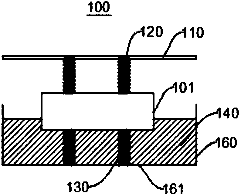
[0035] figure 1 For the overall structure diagram of the flight control damping device 100 provided in the first embodiment of the present invention, please refer to figure 1 .

[0036] The flight control shock absorbing device 100 provided in this embodiment is used for buffering, shock absorbing and fixing the flight control box 101 . The flight control damping device 100 includes a shock absorbing plate 110 , a first support 120 , a second support 130 and a non-Newtonian fluid buffer layer 140 . The first support 120 and the second support 130 are respectively arranged on two sides of the flight control box 101 . One end of the first support 120 is connected to the damping plate 110 , and the other end of the first support 120 is connected to the flight control box 101 . One end of the second support 130 is connected to the flight control box 101 , and the other end of the second support 130 is connected to the non-Newtonian fluid buffer layer 140 .

[0037] Both the fir...

no. 2 example

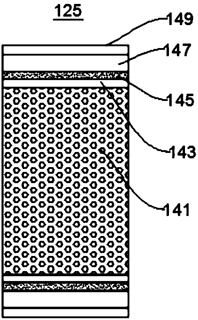
[0045] image 3 For the structural schematic diagram of the non-Newtonian fluid column 125 of the flight control damping device 100 provided in the second embodiment of the present invention, please refer to image 3 .

[0046] In this embodiment, both the first pillar 120 and the second pillar 130 use the non-Newtonian fluid column 125 , and the second pillar 130 is also immersed in the non-Newtonian fluid buffer layer 140 . Preferably, the non-Newtonian fluid column 125 includes a locking splint 147, a buffer strip 145, a waterproof splint 143, an elastic pad 149 and a non-Newtonian fluid layer 141, and the two ends of the non-Newtonian fluid layer 141 are respectively connected to the waterproof splint 143, and the waterproof splint 143 is away from the non-Newtonian fluid layer 143. One side of the Newtonian fluid layer 141 is connected to the buffer strip 145 , and the side of the buffer strip 145 away from the waterproof splint 143 (that is, the buffer strip 145 is away...

no. 3 example

[0059] Figure 6 Another schematic diagram of the overall structure of the flight control damping device 100 provided in the third embodiment of the present invention, please refer to Figure 6 .

[0060]The flight control shock absorbing device 100 provided in this embodiment is used for the flight control box 101, and includes a first shock absorber 111, a second shock absorber 113, a first strut 120 and a second strut 130, the first strut 120 and the second strut 130. The second support 130 adopts the non-Newtonian fluid column 125, of course, it can also include the non-Newtonian fluid column 125 and the spring at the same time. The first shock absorber 111 and the second shock absorber 113 are arranged oppositely, the flight control box 101 is arranged between the first shock absorber 111 and the second shock absorber 113, the first shock absorber 111 and the second shock absorber 113 plays a role of fixing and damping the flight control box 101 . Both ends of the firs...


PUM


Abstract

The invention provides a flight control shock absorption device and an unmanned aerial vehicle, and relates to the technical field of the unmanned aerial vehicle. The flight control shock absorption device is applied to a flight control box. The flight control shock absorption includes a shock absorption plate, a first pillar, a second pillar and a non- Newtonian fluid buffer layer. One end of thefirst pillar is connected with the shock absorption plate, and the other end of the first pillar is connected with the flight control box. One end of the second pillar is connected with flight control box, and the other end of the second pillar is connected with the non- Newtonian fluid buffer layer. The first pillar and the second pillar are correspondingly arranged on both sides of the flight control box. The flight control shock absorption device can play a good role in the shock absorption towards the flight control box, so that the damage to the flight control box during the tumbling process of the unmanned aerial vehicle is avoided, and the operation of the unmanned aerial vehicle is safer and more reliable. The fixing towards the flight control box is achieved, the shock absorptioneffect is achieved, and a stable and reliable working environment for an unmanned aerial vehicle flight control system is provided.

Description

technical field [0001] The invention relates to the technical field of unmanned aerial vehicles, in particular to a flight control shock absorbing device and an unmanned aerial vehicle. Background technique [0002] With the advancement of science and technology and the development of the national economy, the development of unmanned aerial vehicles has become a hot topic at present, and it is used more and more widely. But the UAV is still in the initial stage of development, and there are still many areas that need to be optimized and improved. The flight control system is the core control device of the drone, which is equivalent to the brain of the drone. [0003] In the prior art, the fixing device used for the UAV flight control system is rigidly fixed to ensure that the flight control system can remain relatively still with the fixing device during any rolling operation of the UAV, which can play a role in the flight control system. Good protection and fixation, but ...

Claims


Application Information

Patent Timeline
Patent Type & Authority Applications(China)
IPC IPC(8): B64D47/00F16F13/00F16F9/32F16F9/504
CPCF16F9/006F16F9/3207F16F9/504F16F13/007B64D47/00
Inventor 李秋实秦浩樊晓羽江启峰王磊
Owner 北航(四川)西部国际创新港科技有限公司
Why Eureka
Try Eureka