


Quick Research
Generate reliable direction feasibility study reports for your R&D in just a few steps.

Technical Q&A
Discover and master advanced knowledge NOW. Basics, ideas, possibilities, all at once.

Find Solutions
As an expert in R&D theories, this can generate solutions to your technical problems instantly.

Evaluate Feasibility
Analyze your overall solution with one click, know your potential R&D risks in advance.

Monitor Landscape
Get weekly tech updates, stay abreast of the latest tech innovations and key insights.
Optical lens and car lamp
An optical lens and lens technology, applied in the direction of headlights, motor vehicles, road vehicles, etc., can solve the problems of uneven brightness of pixel spots, sharp borders of vehicle light shape cut-off lines, serious dispersion, etc., so as to reduce dispersion problems and improve connection. Uniformity, the effect of reducing gradients
- Summary
- Abstract
- Description
- Claims
- Application Information
AI Technical Summary
Problems solved by technology
Method used
Image

Examples
Embodiment 1
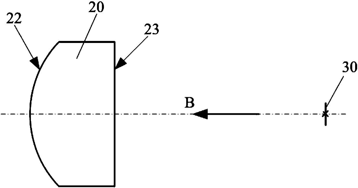
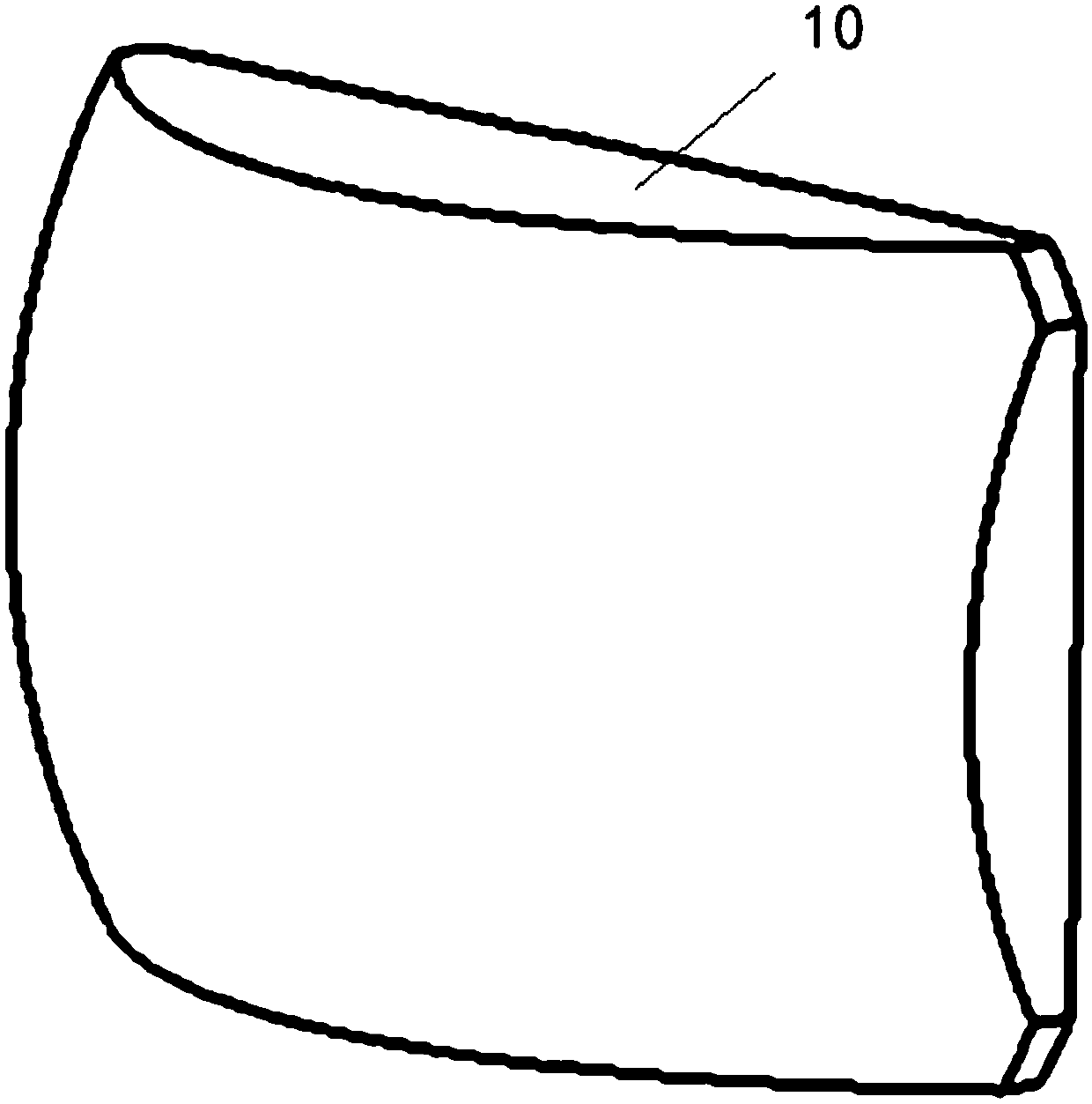
[0040] Such as figure 1 and Figure 4 As shown, the optical lens provided by the embodiment of the present invention includes: a convex lens 20, and the curved side of the convex lens 20 includes a grid area 21, and the grid area 21 is formed by splicing a plurality of polygonal light-transmitting planes.
[0041] The optical lens of the embodiment of the present invention is applied in the lighting device, when the optical lens of the embodiment of the present invention is applied in the optical module of the car light of the automobile, because in the optical lens provided by the embodiment of the present invention, the curved surface of the convex lens 20 The side includes a grid area 21, and the grid area 21 is formed by splicing a plurality of polygonal light-transmitting planes, that is to say, a curved surface formed by splicing a plurality of light-transmitting planes is used to replace the smooth curved surface of the convex lens 20 in the prior art, Since the angles...
Embodiment 2
[0069] Embodiment 2 of the present invention provides a vehicle lamp, and the optical module of the vehicle lamp is provided with the optical lens provided in Embodiment 1 above.
[0070] Since the curved surface side of the convex lens arranged in the optical lens is provided with a grid area, the grid area is formed by splicing a plurality of light-transmitting planes.
[0071] Therefore, when the vehicle lamp provided in the second embodiment is a low beam lamp with a cut-off function, compared with the low beam lamp with a cut-off function in the prior art, the lamp provided in the second embodiment can effectively improve the low beam The gradient and dispersion of the cut-off line can reduce the gradient of the cut-off line for low beams, making the cut-off line softer and reducing the dispersion problem.
[0072] When the car light provided in the second embodiment is a matrix headlight, compared with the matrix headlight in the prior art, in the car light provided in t...
PUM
 Abstract
Description
Claims
Application Information
 - R&D Engineer
- R&D Manager
- IP Professional
- Industry Leading Data Capabilities
- Powerful AI technology
- Patent DNA Extraction
Browse by: Latest US Patents, China's latest patents, Technical Efficacy Thesaurus, Application Domain, Technology Topic, Popular Technical Reports.
© 2024 PatSnap. All rights reserved.Legal|Privacy policy|Modern Slavery Act Transparency Statement|Sitemap|About US| Contact US: help@patsnap.com