
Simply supported beam bridge deck plate continuous structure and construction method thereof

A simply supported girder bridge and construction method technology, applied in the direction of bridges, bridge parts, bridge construction, etc., can solve the problems of poor stability, easy water seepage, easy damage to joints, etc., to achieve good durability, short construction period, labor low intensity effect

Pending Publication Date: 2018-05-15
SHANGHAI MUNICIPAL ENG DESIGN INST GRP
View PDF0 Cites 6 Cited by
  • Summary
  • Abstract
  • Description
  • Claims
  • Application Information

AI Technical Summary

Problems solved by technology

Those skilled in the art have been devoting themselves to the development of a simply supported bridge deck continuous structure and its construction method to overcome the above-mentioned deficiencies. It not only has the advantages of reliable structure and good durability of the common simply supported variable continuous structure, but also can improve the existing structure. It has the disadvantages of easy damage, water seepage, and poor stability at the joints of the simply supported bridge deck connection structure, and has a simple structure, convenient construction, excellent overall performance of the structure, and can ensure the comfort of driving on the bridge, etc.

Method used


Image

  • Simply supported beam bridge deck plate continuous structure and construction method thereof
  • Simply supported beam bridge deck plate continuous structure and construction method thereof
  • Simply supported beam bridge deck plate continuous structure and construction method thereof

Examples


Embodiment 1

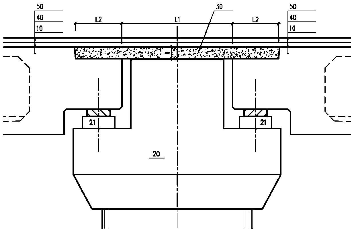
[0029] Supports 21 are respectively provided on the two side wings of the cover beam 20 (inverted T-shaped structure). After the pouring or hoisting of the cover beam 20 is completed, the support 21 is installed, and the main beam 10 is installed above the cover beam 20 through the support 21 to form a simply supported system. During specific implementation, steel bar joints are reserved during the prefabrication of the main girder 10, and after two adjacent main girders 10 are hoisted in place, welded steel bars are erected and concrete is poured to form a continuous slab. Casting continuous slabs on site can effectively avoid the defects of easy cracking and water leakage at the joints, and the structure is simple and the construction is convenient.

[0030] The length of the continuous plate 30 is composed of a slot width L1 and two isolation lengths L2. The slit width L1 refers to the horizontal distance between the beam ends of adjacent main beams 10 on both sides. In th...

Embodiment 2

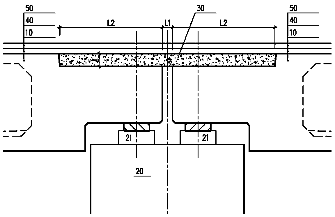
[0034] The difference between the second embodiment and the first embodiment is that the cross-sectional structure of the cover beam 20 is replaced by a rectangular structure, and two sets of supports 21 are arranged at the top of the cover beam 20 (rectangular structure).

[0035] The length of the continuous plate 30 is constituted by the sum of the slot width L1 and the two isolation lengths L2. The slit width L1 refers to the horizontal distance between the beam ends of adjacent main beams 10 on both sides. In this embodiment, since the rectangular structure is arranged below the two main beams 10, the slit width L1 only refers to The horizontal distance between beam ends of adjacent main beams 10 on both sides does not include the width of the rectangular structure.

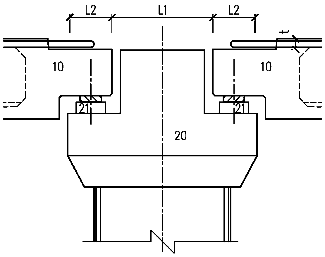
[0036] Adopt the construction method of described simply supported beam bridge deck continuous structure (see image 3 with Figure 4 ), the image 3 with Figure 4 Only the construction steps when the s...


PUM


Abstract

The invention relates to a simply supported beam bridge deck plate continuous structure. The structure comprises a capping beam which is arranged below main beams on the two sides of a bridge deck andfixed to the top of a stand column and a continuous slab arranged between the two adjacent main beams, and the continuous slab is formed through site casting. A construction method of the simply supported beam bridge deck plate continuous structure comprises the following steps that 1, the capping beam is arranged on the top of the stand column; 2, a support is arranged on the capping beam, and the main beam is hoisted on the capping beam, wherein the main beam is in a simply supported state; 3, rebar is bound between the two adjacent main beams, and a layer of the continuous slab is poured.Compared with the prior art, the structure has the advantages that the driving comfort is good, the structural integrity is good, the problem that a present simply supported structure continuous beamis likely to crack and seep can be solved, the structure is simple, and construction is convenient.

Description

technical field [0001] The invention relates to the technical field of bridge structures, in particular to a simply supported bridge deck continuous structure and a construction method thereof. Background technique [0002] The simply-supported girder deck continuous structure is a structure that combines the connecting plate and the main girder to form a continuous bridge deck, and at the same time ensures that the main girder is simply supported. The continuous structure of the bridge deck in simply supported bridges is the weak link of the structure. As far as the structure itself is concerned, since the main girder is a simply supported girder, the continuous structure of the bridge deck is located at the girder end of the main girder, which is the part where the main girder deforms (including rotation and beam expansion and contraction) the most. At present, in the design of multi-span simply supported bridge structures, in order to ensure driving comfort and reduce ex...

Claims


Application Information

Patent Timeline
Patent Type & Authority Applications(China)
IPC IPC(8): E01D19/12E01D21/00
CPCE01D19/125E01D21/00
Inventor 牛长彦卢永成
Owner SHANGHAI MUNICIPAL ENG DESIGN INST GRP
Learn More