Threaded hole repairing drill bit assembly and threaded hole repairing method

A drill assembly and threaded hole technology, applied in the field of threaded hole repair drill assembly, can solve problems such as affecting repair, no space, and inconvenient positioning operation

Active Publication Date: 2018-05-15
CRRC TANGSHAN CO LTD +1
View PDF8 Cites 2 Cited by
  • Summary
  • Abstract
  • Description
  • Claims
  • Application Information

AI Technical Summary

Problems solved by technology

[0004] No matter the first method or the second method, the threaded hole to be repaired needs to be reamed. However, the first method mentioned above requires positioning operation for the electric drill and magnetic drill. Regular tooling, the design and production cycle of this tooling is long, which seriously affects the repair cycle; in addition, the installation space occupied by electric drills and magnetic drills is relatively large, and under some conditions there is no space, which affects repairing, and in special cases, magnetic drills cannot be used. Because the magnetic drill is magnetic, it will demagnetize or change the magnetism of the magnetic parts, so it is not suitable for the repair of the threaded holes of the nearby magnetic parts (such as the repair of the threaded holes on the axle box cover of the bogie turning wall, because the shaft Bearings in the box are magnetic)

Method used


Image

  • Threaded hole repairing drill bit assembly and threaded hole repairing method
  • Threaded hole repairing drill bit assembly and threaded hole repairing method
  • Threaded hole repairing drill bit assembly and threaded hole repairing method

Examples


Embodiment 1

[0051] Figure 1a It is a structural schematic diagram of the threaded hole repair drill assembly provided by Embodiment 1 of the present invention used on parts. Figure 1b It is provided by Embodiment 1 of the present invention Figure 1a Details of part A in Fig. Figure 2a It is a schematic structural view of the first rod-shaped body of the threaded hole repair drill assembly provided by Embodiment 1 of the present invention. Figure 2b It is a front view of the first rod-shaped body of the threaded hole repair drill assembly provided in Embodiment 1 of the present invention. Figure 2c It is a side view of the first rod-shaped body of the threaded hole repair drill assembly provided in Embodiment 1 of the present invention. Figure 3a It is a structural schematic diagram of the second rod-shaped body of the threaded hole repair drill assembly provided by Embodiment 1 of the present invention. Figure 3b It is a front view of the second rod-shaped body of the threaded h...

Embodiment 2

[0080] Figure 7 It is a schematic flow chart of the threaded hole repair method provided in Embodiment 2 of the present invention. Refer to attached Figure 7 As shown, Embodiment 2 of the present invention also provides a threaded hole repair method, comprising the following steps:

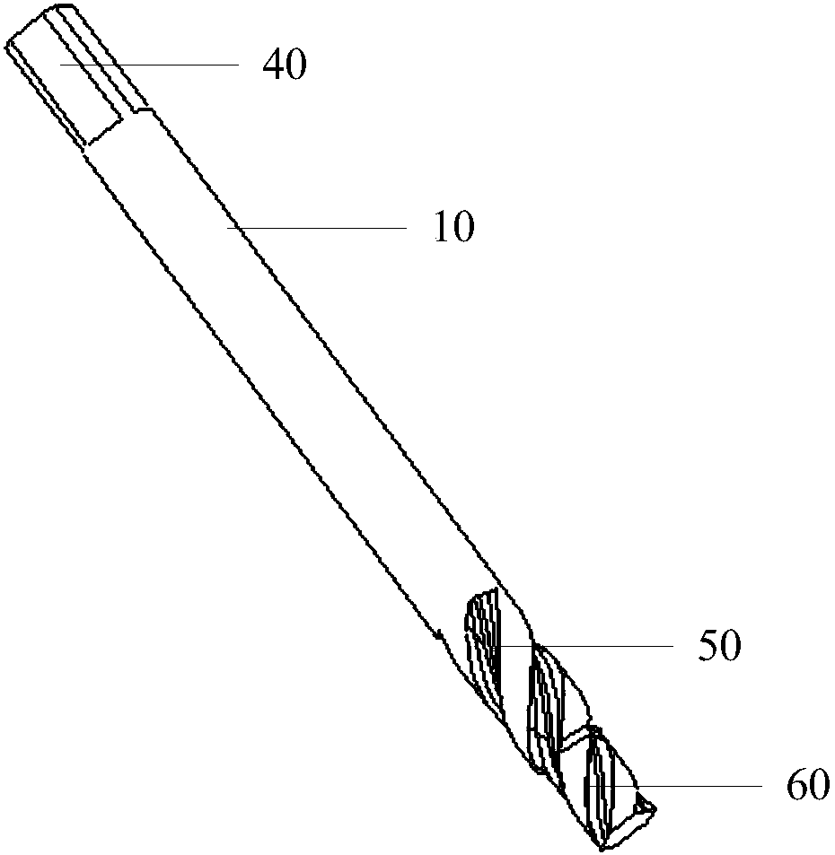
[0081] S1: Insert the first rod-shaped body 10 into the threaded hole to be repaired, use the guide part 60 of the first rod-shaped body 10 and the cutting tool 50 to complete the first reaming of the threaded hole, and take out the first rod-shaped body 10 .

[0082] It should be noted that, in the process of repairing the threaded hole where the thread teeth fall off in this embodiment, the first rod-shaped body 10 is firstly used. One end of the first rod-shaped body 10 has a connecting part 40 connected with the wrench 100, and the second end is provided with a wrench. For the cutting tool 50 for leveling and repairing the inner wall of the threaded hole, a guide part 60 is also provided ...


PUM


Abstract

The invention provides a threaded hole repairing drill bit assembly and a threaded hole repairing method. The threaded hole repairing drill bit assembly comprises a first rod-shaped body, a second rod-shaped body and a third rod-shaped body which are sequentially used in a threaded hole repairing process. The first end of the first rod-shaped body, the first end of the second rod-shaped body and the first end of the third rod-shaped body are provided with connecting portions which are connected with a spanner, the second end of the first rod-shaped body, the second end of the second rod-shapedbody and the second end of the third rod-shaped body are provided with spiral cutting knives, and the diameter of the first rod-shaped body, the diameter of the second rod-shaped body and the diameter of the third rod-shaped body are matched with the inner diameter of a threaded hole. The end portion of the cutting knife of the first rod-shaped body and the end portion of the cutting knife of thesecond rod-shaped body are provided with guide parts used for being clamped into the threaded hole respectively, and the diameter of the guide parts is matched with the tooth top circle of the threaded hole. The threaded hole repairing drill bit assembly can be used for safely and rapidly repairing the threaded hole of which threads are damaged or the threaded hole which does not meet the requirement of a measurement standard.

Description

technical field [0001] The invention relates to the technical field of repairing and processing of large mechanical parts, in particular to a threaded hole repairing drill assembly and a threaded hole repairing method. Background technique [0002] Large parts on railway vehicles will fail during long-term operation. The bogie, as the part with the most accessories on the train, plays a decisive role in driving safety. Therefore, periodic maintenance of the vehicle and the bogie is required. The content of the maintenance mainly includes the connecting threaded holes assembled by the suspension parts. Due to the frequent disassembly during the installation and maintenance process, the thread teeth in the bolt holes of large parts are damaged or do not meet the requirements of the measurement standards (pass through, stop only). ), the threaded holes that do not meet the technical requirements need to be repaired. Due to the extremely cumbersome disassembly and installation ...

Claims


Application Information

Patent Timeline
Patent Type & Authority Applications(China)
IPC IPC(8): B23G5/20B23G1/02B23G9/00
Inventor 杜永强郑建科刘景才廖胡兵荆红伟刘国田刘春海王文玲孟翔飞
Owner CRRC TANGSHAN CO LTD
Why Eureka
Try Eureka