
A low on-state voltage drop igbt and its control method and manufacturing method

An on-state voltage drop, control electrode technology, applied in semiconductor/solid-state device manufacturing, semiconductor devices, electrical components, etc., can solve problems such as poor Trench structure reliability and controllability, increase control flexibility, and increase manufacturing costs. , the effect of improving the feasibility

Active Publication Date: 2021-07-23
GLOBAL ENERGY INTERCONNECTION RES INST CO LTD +1
View PDF4 Cites 0 Cited by
  • Summary
  • Abstract
  • Description
  • Claims
  • Application Information

AI Technical Summary

Problems solved by technology

However, this Trench structure has the disadvantages of poor reliability and controllability

Method used


Image

  • A low on-state voltage drop igbt and its control method and manufacturing method
  • A low on-state voltage drop igbt and its control method and manufacturing method
  • A low on-state voltage drop igbt and its control method and manufacturing method

Examples


Embodiment Construction

[0051] In order to make the purposes, technical solutions and advantages of the embodiments of the present invention clearer, the technical solutions in the embodiments of the present invention will be clearly and completely described below with reference to the accompanying drawings in the embodiments of the present invention. Obviously, the described embodiments These are some embodiments of the present invention, but not all embodiments. Based on the embodiments of the present invention, all other embodiments obtained by those of ordinary skill in the art without creative efforts shall fall within the protection scope of the present invention.

[0052] The following describes a low on-state voltage drop IGBT provided by an embodiment of the present invention with reference to the accompanying drawings.

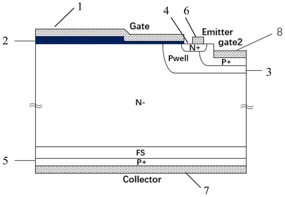
[0053] figure 1 It is a schematic structural diagram of a low on-state voltage drop IGBT in an embodiment of the present invention. As shown in the figure, the low on-stat...


PUM


Abstract

The invention provides a low on-state voltage drop IGBT and its control method and manufacturing method. The low on-state voltage drop IGBT includes a gate, an emitter, a control electrode and a collector; The active region is deposited on the N-type substrate; the collector is deposited on the P+ collector region of the N-type substrate; the control method includes determining its working mode according to the control state of the low on-state voltage drop IGBT. Compared with the prior art, the present invention provides a low on-state voltage drop IGBT and its control method and manufacturing method, which can effectively suppress the flow of holes by controlling the voltage value of the electrodes, thereby increasing the storage capacity of holes in the N-region Reduce the on-state loss of the IGBT.

Description

technical field [0001] The invention relates to the technical field of semiconductors, in particular to a low-on-state voltage drop IGBT, a control method and a manufacturing method thereof. Background technique [0002] Insulated Gate Bipolar Transistor (IGBT) not only has the advantages of unipolar devices and bipolar devices, but also has the advantages of simple driving circuit, low power consumption / cost of control circuit, low saturation voltage and low loss of the device itself. Etc. The IGBT includes a front-side emitter, a gate and a back-side collector. The hole flow of the back-emitting P+ region on the backside is effectively collected in the Pwell base region, and the hole storage capacity of the N- region is relatively low, resulting in poor conductance modulation effect of the IGBT. At the same time, the conductance modulation effect of the IGBT has a great influence on its on-state loss, so in order to reduce the on-state loss of the IGBT, it is necessary to...

Claims


Application Information

Patent Timeline
Patent Type & Authority Patents(China)
IPC IPC(8): H01L29/739H01L29/06H01L29/417H01L21/331H01L21/28
CPCH01L21/28H01L29/0684H01L29/41708H01L29/66325H01L29/7393
Inventor 徐哲温家良金锐王耀华刘江赵哿高明超崔磊潘艳
Owner GLOBAL ENERGY INTERCONNECTION RES INST CO LTD
Learn More