
A nozzle control method, device and computer-readable storage medium

A technology of nozzles and nozzle groups, applied in metal processing equipment, manufacturing tools, coating devices, etc., can solve the problems of time or printing substrate waste, and achieve the effect of improving printing efficiency and

Active Publication Date: 2019-08-23
深圳市东冠包装印刷科技有限公司
View PDF5 Cites 0 Cited by
  • Summary
  • Abstract
  • Description
  • Claims
  • Application Information

AI Technical Summary

Problems solved by technology

[0006] In order to solve the problem in the prior art, the overheating method of the print head is generally that the sensor detects that the inside of the print head reaches the preset temperature threshold, and the printing will be slowed down or stopped, and finally the equipment will be shut down, whether it is to stop the printing or shut down the equipment. All will cause waste of time or printing substrate technical defects, the present invention proposes a nozzle control method, the method includes:

Method used


Image

  • A nozzle control method, device and computer-readable storage medium
  • A nozzle control method, device and computer-readable storage medium
  • A nozzle control method, device and computer-readable storage medium

Examples


Embodiment 1

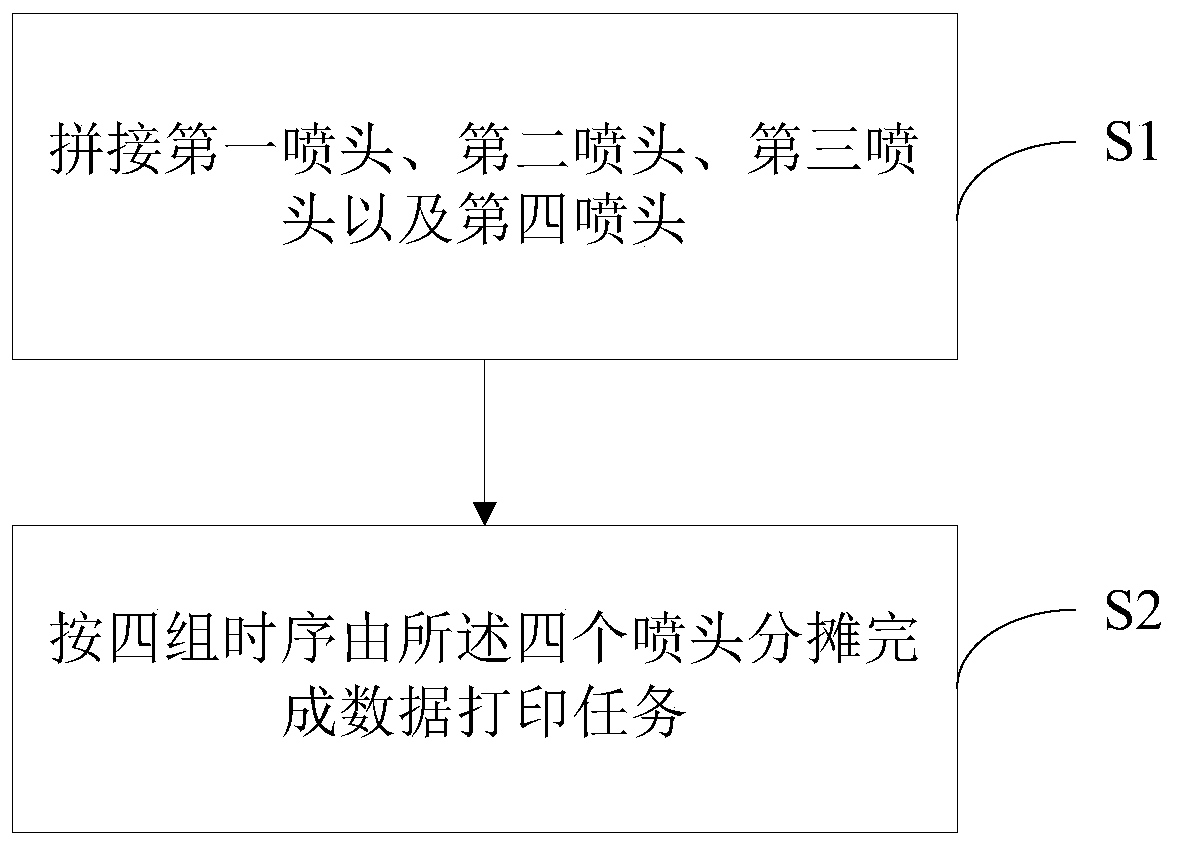
[0030] figure 1 It is a flow chart of the first embodiment of the nozzle control method of the present invention. A nozzle control method, the method comprising:

[0031] S1. Splicing the first nozzle, the second nozzle, the third nozzle and the fourth nozzle. Wherein, the first nozzle and the second nozzle are horizontally spliced, the third nozzle and the fourth nozzle are horizontally spliced, the first nozzle and the third nozzle are vertically spliced, and the first nozzle is spliced ​​vertically. The second nozzle and the fourth nozzle are longitudinally spliced;

[0032] S2. The four print heads share and complete the data printing task according to four groups of time sequences. Wherein, the first data is printed by the first nozzle and the third nozzle of the first nozzle at the first moment, the third data is printed by the fifth nozzle and the seventh nozzle of the second nozzle at the second moment, and the third data is printed by the fifth nozzle and the seven...

Embodiment 2

[0058] Based on the above-mentioned embodiments, this embodiment proposes a rotation rest mechanism in the case of overheating of the nozzles: on the one hand, when the temperature of one or two nozzles in the non-same direction exceeds the set alarm threshold, the set There should be a certain margin for the alarm threshold, so that it can continue to work for a short period of time. On the other hand, if the alarming nozzle needs to take a rest in rotation, a mechanism for the nozzle to take a rest in rotation should be set.

[0059] In this embodiment, it is first necessary to solve the finishing work of the data printing task when the nozzle is overheated, specifically:

[0060] When overheating occurs during the printing process of the nozzle, directly call the data of the second half of this task. In order to achieve the seamless connection of data, it is necessary to count the number of printing frames. Once the nozzle is overheated, the minimum black block unit (such a...

Embodiment 3

[0065] In the above embodiment, when the nozzle is overheated, the finishing work of the data printing task when the nozzle is overheating is solved. In this embodiment, after the finishing work of the data printing task is completed, the working state of the nozzle is switched, specifically :

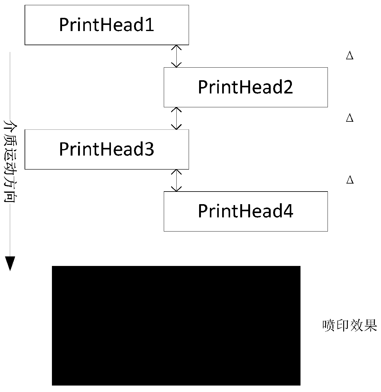
[0066] Such as figure 2 Shown is a schematic diagram of nozzle splicing in the nozzle control method of the present invention. If one of the four nozzles is overheated, the four nozzles are grouped, wherein:

[0067] The first spray head and the second spray head are in a first group;

[0068] The first spray head and the fourth spray head are in the second group;

[0069] The third nozzle and the second nozzle are in a third group;

[0070] The third spray head and the fourth spray head are in a fourth group.

[0071] It can be understood that, among the above four groups, any group of nozzles can independently complete the data printing task.

[0072] Further, if one of the fou...


PUM


Abstract

A spray head control method, comprising: joining a first spray head, a second spray head, a third spray head and a fourth spray head, wherein the first spray head and the second spray head are transversely joined, the third spray head and the fourth spray head are transversely joined, the first spray head and the third spray head are vertically joined, and the second spray head and the fourth spray head are vertically joined; proportioning and completing data printing tasks by means of the four spray heads according to four groups of timing sequences, wherein a first nozzle and a third nozzle of the first spray head print first data at a first moment, a fifth nozzle and a seventh nozzle of the second spray head print third data at a second moment, a second nozzle and a fourth nozzle of the third spray head print second data at a third moment, and a sixth nozzle and an eighth nozzle of the fourth spray head print fourth data at a fourth moment. By means of rationally controlling spray heads and nozzles, the full quantity of nozzles of the spray heads may be used, and printing speed and printing quality are not reduced due to a spray head alarm; meanwhile, the control method may guarantee that the spray head stops in case of an overheating alarm, and may guarantee that the movement of a medium is not interrupted, thereby improving the printing efficiency and usage ratio of a printing device.

Description

technical field [0001] The invention relates to the technical field of printing, in particular to a method for controlling a nozzle. Background technique [0002] In the prior art, in the operation and use of industrial inkjet printing equipment, the application of unconventional printing is increasing day by day, such as the production of liquid crystal screens and the production of thin film circuits. As the batch production method of graphene slurry becomes more and more mature, the production of graphene film (non-single-layer film) by jet printing has also become a reality. [0003] Graphene films have many advantages, such as good thermal conductivity and strong electrical conductivity, and the important prerequisite for these advantages is that the thickness of the film should be thin. Industrial nozzles can realize high-precision, high-speed, and small-dose liquid injection (ink-like solutions that meet the requirements of nozzles). The graphene slurry is configure...

Claims


Application Information

Patent Timeline
Patent Type & Authority Patents(China)
IPC IPC(8): B29C64/112B29C64/209B29C64/393B33Y30/00B33Y50/02
Inventor 韩业实瞿浩正宋宇
Owner 深圳市东冠包装印刷科技有限公司
Learn More