
A Creep Constitutive Model Parameter Identification Method for Creep Test

A constitutive model and parameter identification technology, applied in the field of material constitutive model and mechanical behavior, can solve problems such as difficult to accurately predict material creep behavior

Active Publication Date: 2020-07-07
HEFEI GENERAL MACHINERY RES INST +1
View PDF4 Cites 0 Cited by
  • Summary
  • Abstract
  • Description
  • Claims
  • Application Information

AI Technical Summary

Problems solved by technology

[0004] In order to overcome the deficiencies of the above-mentioned prior art, the object of the present invention is to solve the problem that it is difficult to accurately predict the creep behavior of materials in the prior art. For this reason, the present invention provides a creep constitutive model parameter identification for creep tests method

Method used


Image

  • A Creep Constitutive Model Parameter Identification Method for Creep Test
  • A Creep Constitutive Model Parameter Identification Method for Creep Test
  • A Creep Constitutive Model Parameter Identification Method for Creep Test

Examples


Embodiment 1

[0046] A creep constitutive model parameter identification method for creep tests, comprising the following steps:

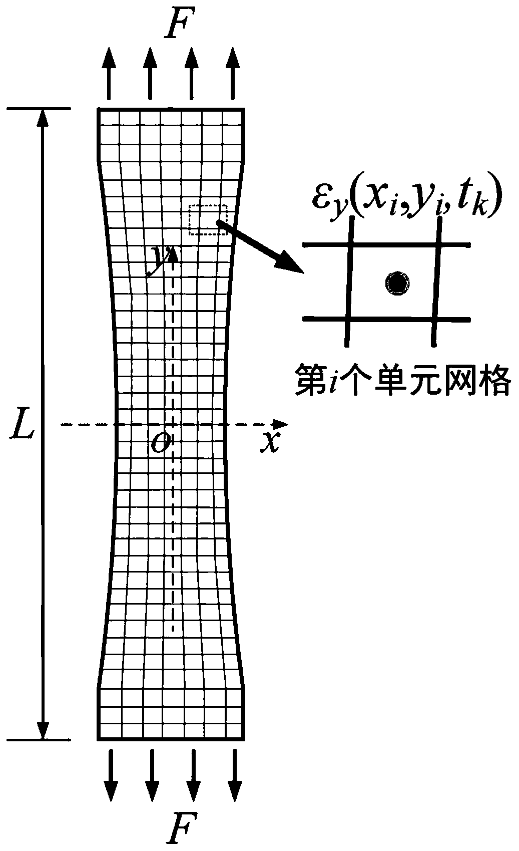
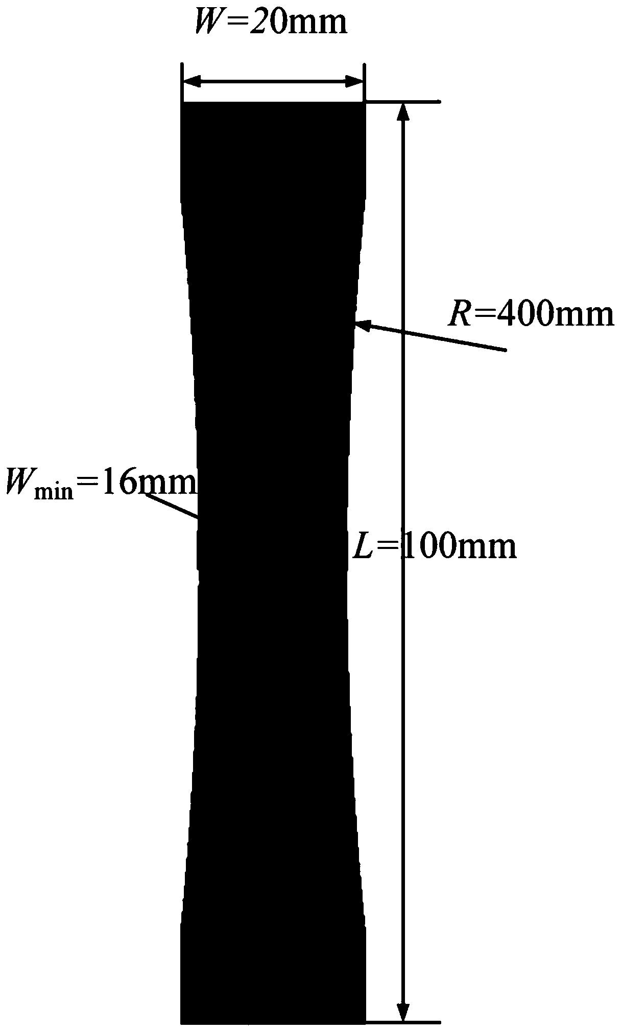
[0047]S1: In the creep test of the sample material based on the variable cross-section specimen, the variable cross-section specimen is subjected to the creep load F. The selected sample is a plate-shaped sample with a set thickness. The three adjacent and perpendicular surfaces in the plate-shaped sample are the sample analysis surface, the longitudinal section in the thickness direction and the creep load F acting surface respectively. The analysis surface of the sample is parallel to the direction of the creep load F acting on the sample, and the direction of the creep load F is set as the y direction. Such as Figure 1-2 As shown, the sample material is carbon-manganese steel SA-210C, the sample thickness H is 1 mm, the width W of the sample at the creep load F loading end is 20 mm, and the sample length L is 100 mm. The sample analysis surface is the surf...

Embodiment 2

[0075] Under the same environment of embodiment 1, the creep load F2 along the y direction is applied to carbon-manganese steel SA-210C, the force of F2 is different from the creep load F in embodiment 1, and the same 1600 in embodiment 1 are measured respectively test point at t k =50, 100, 150, 200, 250, 300, 350, 400, 450, 500h, and the finally obtained measurement value conforms to formula (13).


PUM


Abstract

The invention discloses a creep constitutive model parameter identification method for creep test. The method includes the steps: extracting a strained measuring value epsilon y (xi, yi and tk) of ani measuring point of a sample analysis surface at a k strained measuring moment tk by a creep load F in a y direction to obtain a creep strain of the i measuring point of the sample analysis surface at the moment tk as shown in the specification; determining a grid area Ai taking the i measuring point as a center; selecting a creep constitutive model, and enabling the creep strainepsilon <cr> to express a function of stress level sigma and creep time t; acquiring virtual work under the action of the creep load F; acquiring an objective function phi (p) for identifying creep constitutive model parameters, and solving a value popt and a parameter popt of a corresponding p of a minimal value of the objective function. The corresponding parameter popt is an identified creep constitutive model parameter. The method has the advantages that sample material creep deformation behaviors can be forecasted according to stress conditions without change of materials and environmental conditions.

Description

technical field [0001] The invention relates to the technical field of material constitutive models and mechanical behaviors, in particular to a creep constitutive model parameter identification method for creep tests. Background technique [0002] In industrial fields such as petrochemical, electric power and aerospace, equipment such as pressure vessels, power generation boilers, steam turbines and gas turbines are subjected to high temperature loads for a long time. With the rapid development of industrial technology and the continuous adjustment of energy structure, the service parameters of these high-temperature equipment are developing towards extremes. Ensuring their intrinsic safety during long-term operation has become a very prominent issue in my country's industrial development. Under high temperature conditions, creep deformation and fracture become important failure modes that limit the service life of high temperature equipment. However, due to the long time-...

Claims


Application Information

Patent Timeline
Patent Type & Authority Patents(China)
IPC IPC(8): G06F30/20
CPCG06F30/20
Inventor 周煜范志超陈学东江慧丰刘孝亮薛吉林
Owner HEFEI GENERAL MACHINERY RES INST
Learn More