Non-contact dynamic stiffness measurment system and method thereof

A non-contact, measurement system technology, applied in the direction of measuring devices, elastic testing, machine/structural component testing, etc., can solve problems such as misjudgment of maintenance, inability to predict the characteristics of the spindle, and the inability to measure the dynamic characteristics of the spindle

Inactive Publication Date: 2018-05-08
IND TECH RES INST
View PDF5 Cites 7 Cited by
  • Summary
  • Abstract
  • Description
  • Claims
  • Application Information

AI Technical Summary

Problems solved by technology

However, the dynamic characteristics of the spindle in the static state and the rotating state are not the same, and the general static percussion test cannot be applied to the dynamic characteristic measurement of the rotating spindle, and the characteristics of the rotating spindle cannot be predicted.
The common damage factors of the spindle mostly come from the variation of the bearing, but the rigidity of the bearing shows a non-linear change with the change of the speed and is difficult to measure directly, which may easily lead to misjudgment of maintenance

Method used


Image

  • Non-contact dynamic stiffness measurment system and method thereof
  • Non-contact dynamic stiffness measurment system and method thereof
  • Non-contact dynamic stiffness measurment system and method thereof

Examples


Embodiment Construction

[0059] The detailed features and advantages of the present invention are described in detail below in the embodiments, the content of which is sufficient to enable anyone familiar with the relevant art to understand the technical content of the present invention and implement it accordingly, and according to the content disclosed in this specification, the scope of claims and the accompanying drawings , anyone skilled in the art can easily understand the related objects and advantages of the present invention. The following examples further illustrate the concept of the present invention in detail, but do not limit the scope of the present invention in any way.

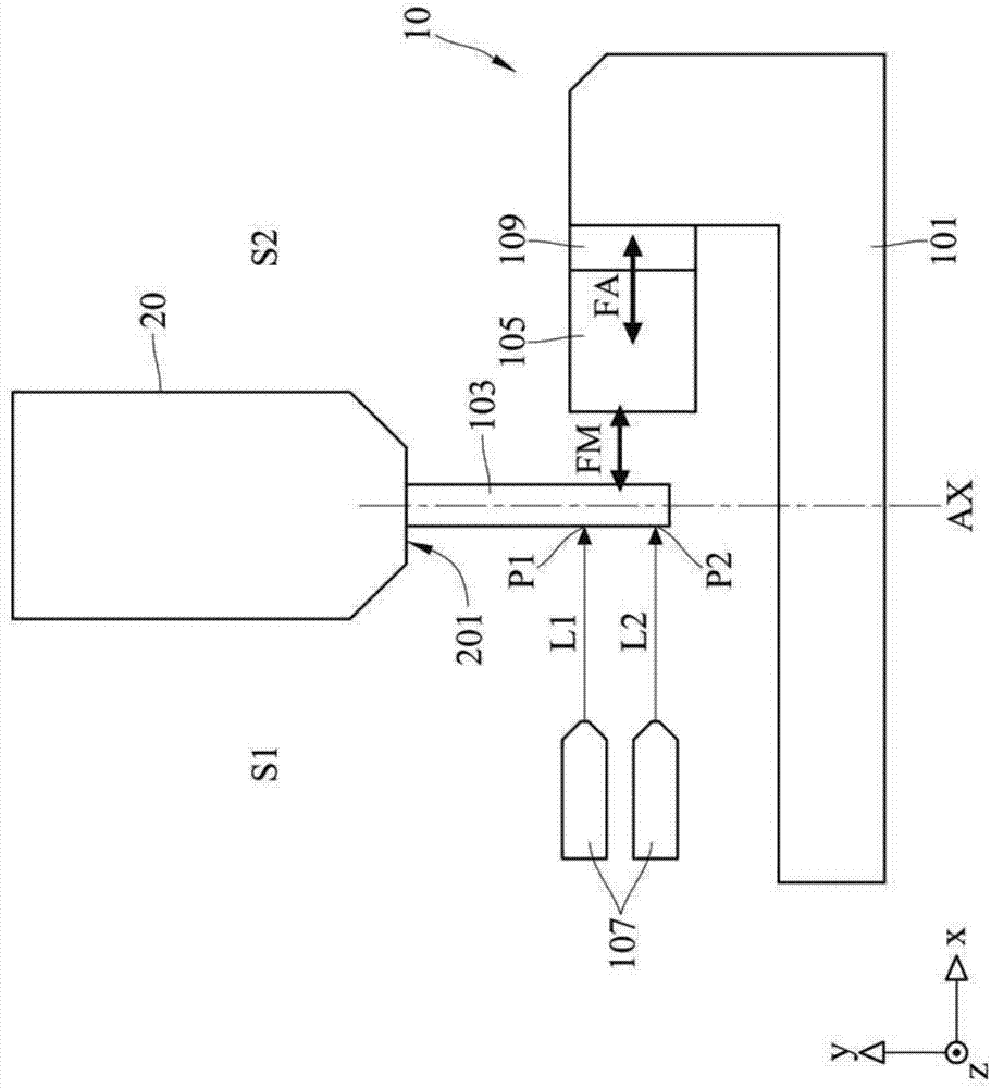
[0060] Please refer to Figure 1A , Figure 1A It is a schematic diagram of relative positions of various components of the non-contact dynamic stiffness measurement system in an embodiment of the present invention. Such as Figure 1A As shown, the non-contact dynamic stiffness measurement system 10 has a base 101 , a...


PUM


Abstract

The invention discloses a non-contact dynamic stiffness measurement system and a method thereof. The non-contact dynamic stiffness measurement system includes a base, a test bar, an exciter, a force sensor, a laser Doppler velocimeter, and a controller. The force sensor is connected to the exciter and the base. The exciter is located between the test bar and the force sensor. The controller is electrically connected to the force sensor and the laser Doppler velocimeter. The test bar is detachably set in a holder of the main shaft under test. The exciter provides an electromagnetic force to thetest bar. The force sensor measures the acting force of the exciter. The laser Doppler velocimeter provides a first laser beam and a second laser beam. The laser Doppler velocimeter measures a vibration response with reflected laser beams. The controller determines an equivalent main shaft stiffness value of the main shaft under test according to the acting force and the vibration response.

Description

technical field [0001] The present invention relates to a dynamic stiffness measurement system and method, in particular to a non-contact dynamic stiffness measurement system and method for a machine tool spindle or a rotating shaft. Background technique [0002] The machine tool provides power to make the workpiece and the tool move relative to each other, and cut the excess metal of the workpiece to produce precision parts. Generally speaking, the machine tool rotates the clamped tool through the spindle to provide cutting force. Therefore, the structure of the machine tool must be rigid enough to enable the tool to provide stable cutting force when cutting the workpiece to achieve the expected accuracy. [0003] At present, most of the common rigidity testing methods are to measure the main shaft when the main shaft is stationary. However, the dynamic characteristics of the spindle in the static state and the rotating state are not the same, and the general static percus...

Claims


Application Information

Patent Timeline
Patent Type & Authority Applications(China)
IPC IPC(8): G01M5/00
CPCG01M5/0091G01N29/07G01N29/2418G01N29/2412G01N2291/02827G01N29/041
Inventor 戴仲裕盖震宇彭达仁陈逸轩
Owner IND TECH RES INST
Why Eureka
Try Eureka