
Novel indicator pull force tester

A tension test and indicator technology, applied in the direction of tension measurement, etc., can solve the problems of cumbersome test process, poor precision, high cost investment, etc., and achieve the effect of stable overall structure design, small measurement error, and reduced cost investment

Active Publication Date: 2018-05-08
TIANJIN HAOYUAN HUINENG TECH CO LTD
View PDF5 Cites 1 Cited by
  • Summary
  • Abstract
  • Description
  • Claims
  • Application Information

AI Technical Summary

Problems solved by technology

[0004] In view of this, the present invention aims to solve the problem of poor accuracy, high cost investment and cumbersome testing process when the existing tensile testing machine performs the tensile test.

Method used


Image

  • Novel indicator pull force tester
  • Novel indicator pull force tester
  • Novel indicator pull force tester

Examples


Embodiment Construction

[0044] It should be noted that, in the case of no conflict, the embodiments of the present invention and the features in the embodiments can be combined with each other.

[0045] In describing the present invention, it should be understood that the terms "center", "longitudinal", "transverse", "upper", "lower", "front", "rear", "left", "right", " The orientations or positional relationships indicated by "vertical", "horizontal", "top", "bottom", "inner" and "outer" are based on the orientations or positional relationships shown in the drawings, and are only for the convenience of describing the present invention and Simplified descriptions, rather than indicating or implying that the device or element referred to must have a particular orientation, be constructed and operate in a particular orientation, and thus should not be construed as limiting the invention. In addition, the terms "first", "second", etc. are used for descriptive purposes only, and should not be understood ...


PUM


Abstract

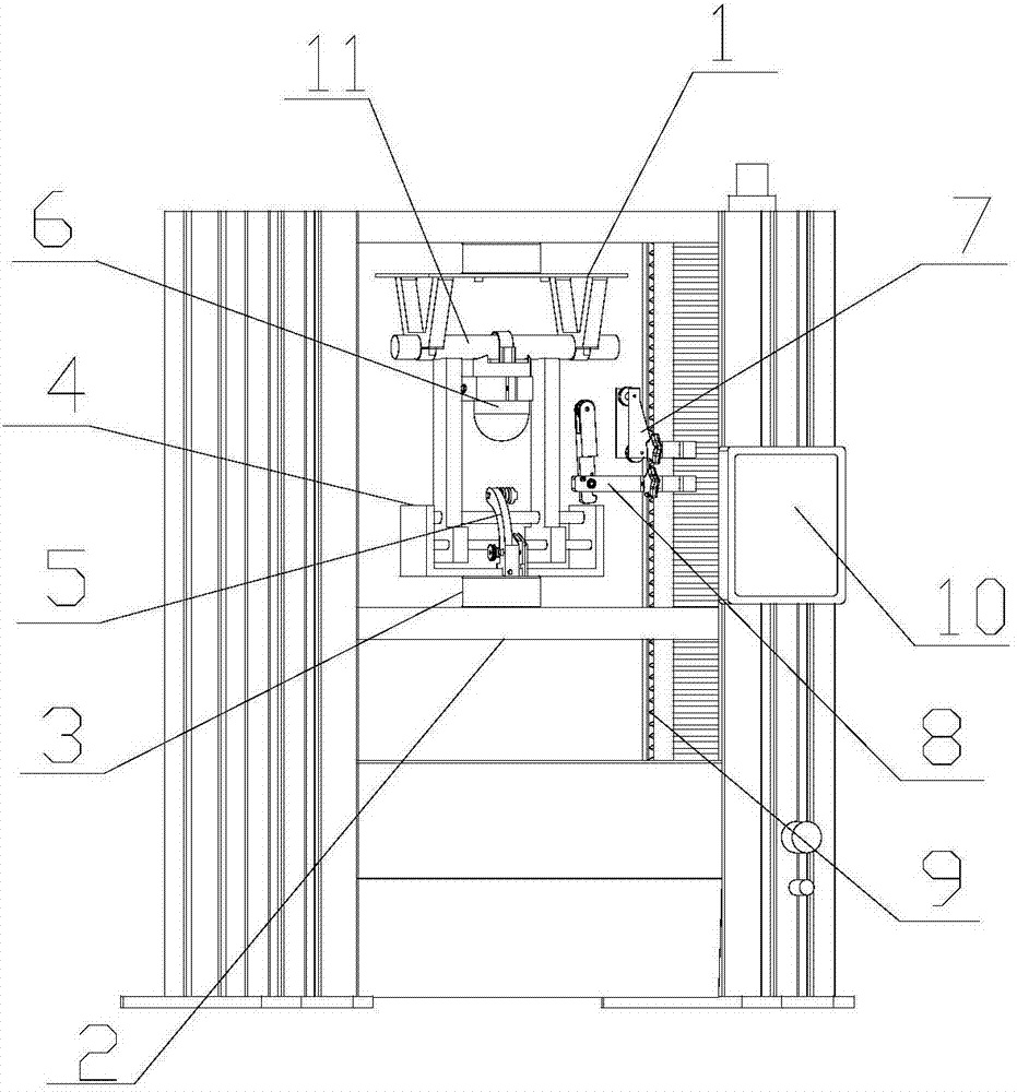
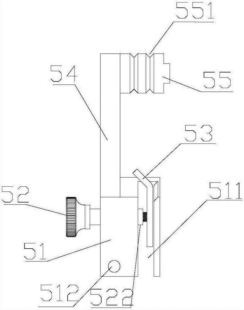
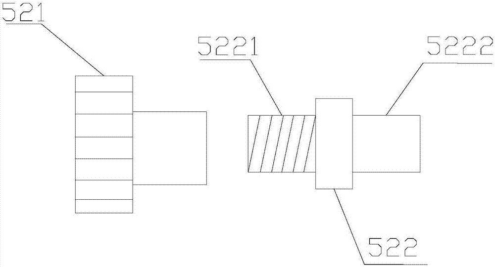
The invention provides a novel indicator pull force tester including a body. A vertical fixing device is arranged on each of the two sides of the body. A box structure is arranged between the bottomsof the two vertical fixing devices, and the box structure is used for placing a motor and a control system. A fixed beam is arranged between the tops of the two vertical fixing devices. An indicator fixing frame is fixed below the fixed beam. An indicator is placed below the indicator fixing frame. A movable plate is arranged below the indicator, and the movable plate is horizontally arranged between the two vertical fixing devices. A pressure sensor is fixed above the movable plate. A down-pull force test tool is arranged above the pressure sensor. A steel wire fixing guide tool is fixed to the down-pull force test tool. The novel indicator pull force tester of the invention can accurately measure the side-pull force and down-pull force which can be borne by the indicator. Only one motoris needed. The cost input is reduced. The overall structure design is stable. The measuring precision is high.

Description

technical field [0001] The invention belongs to the technical field of testing equipment, and in particular relates to a novel indicator tensile testing machine. Background technique [0002] Indicators are often used in power detection, such as wave recording fault indicators, short-circuit indicators, grounding indicators, etc. Most of the existing indicators are hung on the cable by means of hooks for the convenience of installation and disassembly , the hook will open under a certain external force, and the indicator will fall off. When the indicator falls off accidentally by external force such as wind, not only the indicator may be broken, but also people or animals below may be hit , causing casualties; therefore, it is necessary to perform a pull test on the indicator before use, and measure the indicator's ability to withstand the ultimate pull force and side pull force. [0003] Most of the existing test tools have poor precision, high overall cost investment, and...

Claims


Application Information

Patent Timeline
Patent Type & Authority Applications(China)
IPC IPC(8): G01L5/06
CPCG01L5/06
Inventor 王斌
Owner TIANJIN HAOYUAN HUINENG TECH CO LTD
Learn More