
Permanent-magnet type self-locking valve

A self-locking valve, permanent magnet technology, applied in the field of solenoid valves, can solve the problems of low permanent magnet locking retention force, short continuous working life, sealing failure, etc., so as to reduce the structure of connecting fasteners and improve the anti-pollution ability. , Improve the effect of sealing reliability

Inactive Publication Date: 2018-05-08
BEIJING RES INST OF PRECISE MECHATRONICS CONTROLS
View PDF5 Cites 5 Cited by
  • Summary
  • Abstract
  • Description
  • Claims
  • Application Information

AI Technical Summary

Problems solved by technology

[0004] 1) Complex structure, heavy weight, large volume, and poor maintainability, which cannot meet the requirements of compact structure, light weight, and miniaturization of aerospace vehicles
[0005] 2) The working reliability is low, the continuous working life is short, and it cannot meet the service life requirements of the aerospace field
[0006] 3) The retention force of the permanent magnetic lock is low, and the seal failure or even state change occurs under complex mechanical environmental conditions

Method used


Image

  • Permanent-magnet type self-locking valve
  • Permanent-magnet type self-locking valve
  • Permanent-magnet type self-locking valve

Examples


Embodiment Construction

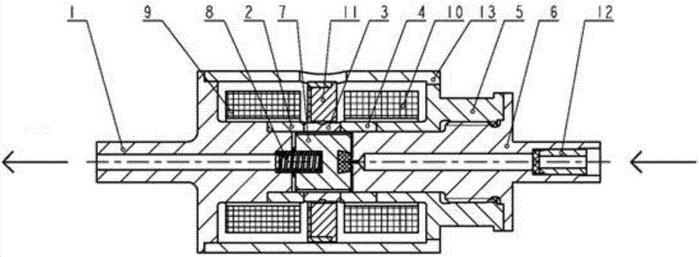
[0024] A permanent magnet self-locking valve provided by the present invention will be further described in detail below in conjunction with the accompanying drawings and specific embodiments.

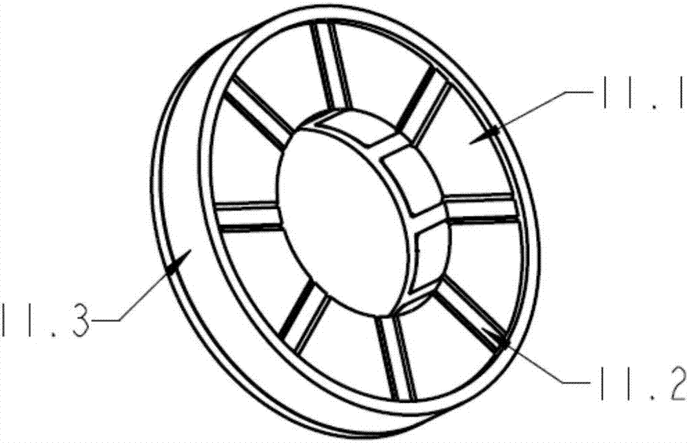
[0025] Such as figure 1 As shown, a permanent magnet self-locking valve provided by the present invention includes an outlet pipe 1, a magnetic isolation ring 1 2, a magnetic conduction ring 3, a magnetic isolation ring 2 4, a right skeleton 5, an inlet pipe 6, a valve core 7, Spring 8, opening coil 9, closing coil 10, permanent magnet assembly 11, filter assembly 12, housing 13;

[0026] The outlet pipe 1, the magnetic isolation ring 1 2, the magnetic conduction ring 3, the magnetic isolation ring 2 4 and the right frame 5 are respectively connected by welding to form a coil frame; the permanent magnet assembly 11 is set on the outer circle of the magnetic conduction ring 3 and opened The coil 9 and the closing coil 10 are wound on the outer circle of the welded coil frame, and are l...


PUM


Abstract

The invention belongs to the technical field of self-locking valves, and particularly relates to a permanent-magnet type self-locking valve. According to the permanent-magnet type self-locking valve,an outlet pipe, a first magnetic insulation ring, a magnetic guiding ring, a second magnetic insulation ring and a right skeleton are connected in a welded mode to form a coil skeleton; a permanent magnet assembly is arranged on the outer circle of the magnetic guiding ring in a sleeving mode, and a staring coil and a closing coil are wound around the outer circle of the coil skeleton and are located on the left side and the right side of the permanent magnet assembly correspondingly; the coil skeleton is sleeved with a shell, and the shell is connected with the outlet pipe and the right skeleton in a welded mode; a valve core is located in an inner hole formed by the first magnetic insulation ring, the magnetic guiding ring and the second magnetic insulation ring, and a spring is arrangedbetween the outlet pipe and the valve core; an inlet pipe is screwed into the right skeleton, the juncture of outer circles of the inlet pipe and the right skeleton are welded and fixed; and a filterassembly is fixedly mounted in an inlet pipe inner hole. The permanent-magnet type self-locking valve has the characteristics of the compact structure, the low weight, the small size, the high reliability of the whole valve and the high anti-pollution ability.

Description

technical field [0001] The invention belongs to the technical field of electromagnetic valves, in particular to a permanent magnet self-locking valve. Background technique [0002] As an electromagnetic switch element, the self-locking valve is widely used in the industrial and aerospace fields. Usually its self-locking methods include mechanical self-locking, permanent magnetic self-locking and so on. Due to its simple structure, high reliability, compact size and many other advantages, the permanent magnet double-position self-locking valve has been more and more widely used in the civil industry and the aerospace field. [0003] The bistable permanent magnet self-locking valve of the prior art mainly has the following problems: [0004] 1) The structure is complex, heavy, bulky, and poor in maintainability, which cannot meet the requirements of compact structure, light weight, and miniaturization of aerospace vehicles. [0005] 2) The working reliability is low, the co...

Claims


Application Information

Patent Timeline
IPC IPC(8): F16K31/06
CPCF16K31/06
Inventor 马晓琛李国强韦贯举苏静静
Owner BEIJING RES INST OF PRECISE MECHATRONICS CONTROLS
Learn More