Storage battery outer shell two-point glue injection hot runner structure, injection molding method and injection molding machine

A technology for batteries and outer casings, which is applied to battery boxes/jackets, structural parts, battery pack parts, etc. It can solve the problems of high mold opening cost, long molding cycle, and core eccentricity, so as to realize automatic production and reduce development costs. The effect of reducing mold cost and saving production cost

Pending Publication Date: 2018-05-08
宁波亚圣自动化科技有限公司
View PDF0 Cites 1 Cited by
  • Summary
  • Abstract
  • Description
  • Claims
  • Application Information

AI Technical Summary

Problems solved by technology

[0003] Among them, the disadvantages of the three-plate mold cold runner injection molding structure are serious waste of plastic raw materials, long molding cycle, obvious color difference in product appearance and unfavorable for automatic production
[0004] The defect of the seven-point hot runner injection molding structure is that the initial mold opening cost is relatively large, because the mold opening cost of the hot runner industry is usually billed by points
In the prior art, a time controller is generally used to control the g...

Method used


Image

  • Storage battery outer shell two-point glue injection hot runner structure, injection molding method and injection molding machine
  • Storage battery outer shell two-point glue injection hot runner structure, injection molding method and injection molding machine
  • Storage battery outer shell two-point glue injection hot runner structure, injection molding method and injection molding machine

Examples


Embodiment Construction

[0041] In order to make the purpose, technical solution and advantages of the present invention clearer, the technical solution of the present invention will be described in detail below. Apparently, the described embodiments are only some of the embodiments of the present invention, but not all of them. Based on the embodiments of the present invention, all other implementations obtained by persons of ordinary skill in the art without making creative efforts fall within the protection scope of the present invention.

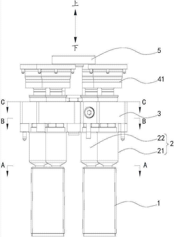
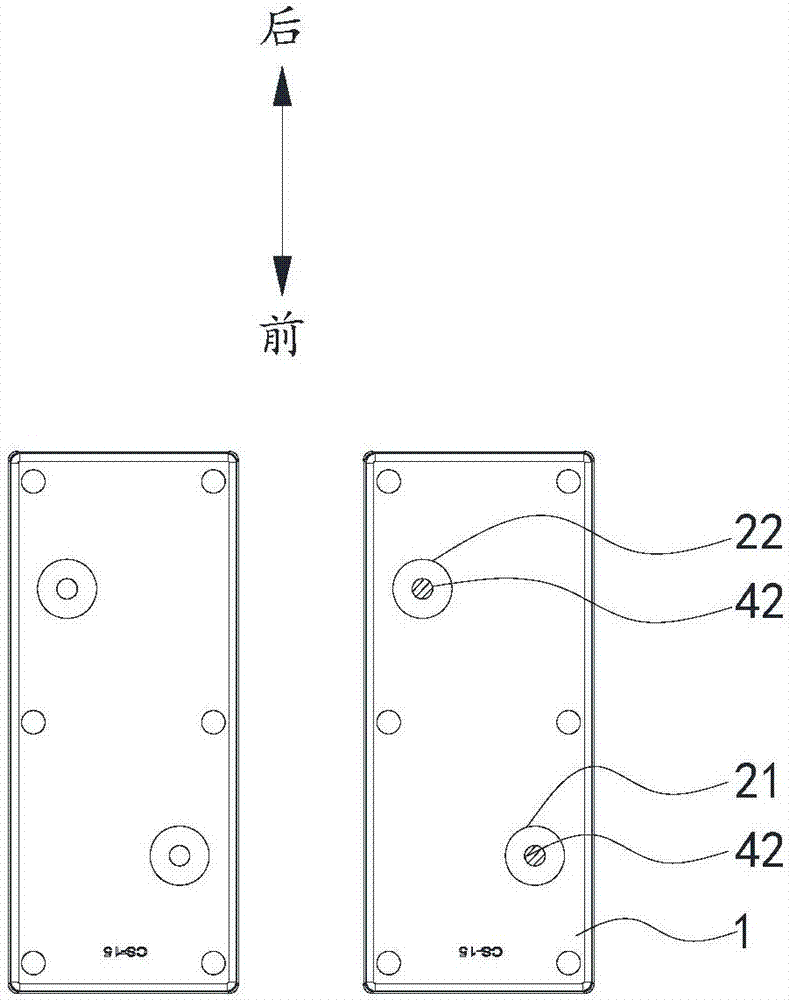
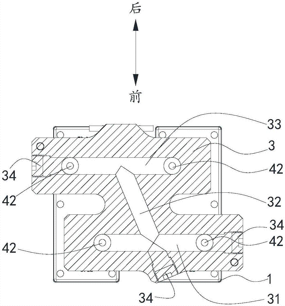
[0042] The first aspect of the present invention provides a two-point glue injection hot runner structure for the battery case 1, which is used for casting the battery case 1 . It includes two hot nozzles 2, a splitter plate 3, a driving mechanism and an injection nozzle 5 for injecting glue. The two hot nozzles 2 are arranged symmetrically front and back with respect to the center position of the top surface of the battery case 1 . The lower ends of the two hot...


PUM


Abstract

The invention provides a storage battery outer shell two-point type glue injection hot runner structure, and relates to the technical field of plastic injection molding, the technical problem of how to enable the storage battery outer shell to be subjected to balance injection molding is solved. The structure comprises two hot nozzles, a flow-dividing plate, a driving mechanism and an injection nozzle for injecting glue, the two hot nozzles are arranged in a front-and-back mode relative to the center position of the top surface of the storage battery shell, and the lower ends of the two hot nozzles are positioned on the diagonal lines of the top surface of the storage battery shell; the lower end of the flow-dividing plate is connected and communicates with the upper ends of the two hot nozzles; the driving mechanism is connected with the upper end of the flow-dividing plate, is positioned on the two sides of the injection nozzle, and synchronously drives the two hot nozzles to be opened or closed; the injection nozzle is positioned in the center of the upper end of the flow-dividing plate, is connected with the flow-dividing plate and communicates with the flow-dividing plate, andthe injection nozzle is in equal-distance communication with the two hot nozzles through the flow-dividing plate; and the injection nozzle is used for injecting the colloid into the flow-dividing plate and simultaneously flows out of the two hot nozzles at the same time to complete the balanced glue discharging.

Description

technical field [0001] The invention relates to the technical field of plastic injection molding, in particular to a two-point glue-injecting hot runner structure for a storage battery casing, an injection molding method and an injection molding machine. Background technique [0002] For the injection molding of the battery outer casing, the traditional three-plate mold cold runner injection molding structure or the seven-point hot runner injection molding structure are usually used. [0003] Among them, the disadvantages of the three-plate mold cold runner injection molding structure are serious waste of plastic raw materials, long molding cycle, obvious color difference in product appearance and unfavorable for automatic production. [0004] The disadvantage of the seven-point hot runner injection molding structure is that the mold opening cost is relatively high in the early stage, because the mold opening cost of the hot runner industry is usually billed by points. For ...

Claims


Application Information

Patent Timeline
IPC IPC(8): B29C45/27B29C45/28H01M2/02H01M50/10
CPCB29C45/27B29C45/28H01M50/10Y02E60/10
Inventor 赵昌银
Owner 宁波亚圣自动化科技有限公司
Why Eureka
Try Eureka