


Quick Research
Generate reliable direction feasibility study reports for your R&D in just a few steps.

Technical Q&A
Discover and master advanced knowledge NOW. Basics, ideas, possibilities, all at once.

Find Solutions
As an expert in R&D theories, this can generate solutions to your technical problems instantly.

Evaluate Feasibility
Analyze your overall solution with one click, know your potential R&D risks in advance.

Monitor Landscape
Get weekly tech updates, stay abreast of the latest tech innovations and key insights.
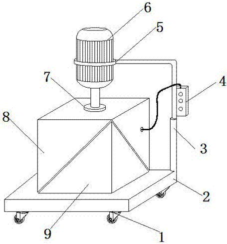
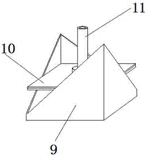
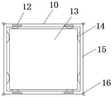
Device with high safety performance for pressing rubber
A safety performance and rubber technology, applied in the field of pressing devices, can solve the problems of hidden dangers of processing personnel, slow down the progress of forging, and low screw efficiency, and achieve the effects of increasing service life, improving pressing efficiency, and improving plasticity
- Summary
- Abstract
- Description
- Claims
- Application Information
AI Technical Summary
Problems solved by technology
Method used
Image

Examples
Embodiment Construction
[0019] The following will clearly and completely describe the technical solutions in the embodiments of the present invention with reference to the accompanying drawings in the embodiments of the present invention. Obviously, the described embodiments are only some, not all, embodiments of the present invention.
[0020] refer to Figure 1-3 , a device for pressing rubber with high safety performance, including a base 2, universal wheels 1 are fixed by screws at the four corners of the outer wall of the bottom of the base 2, and a lower engaging box 9 is welded on the central axis of the outer wall of the top of the base 2, the base 2 A corner of the top outer wall is welded with an electric telescopic rod 3, and the top outer wall of the electric telescopic rod 3 is welded with a connecting rod, the outer wall of the connecting rod is fixed with a controller 4 by screws, and the end of the connecting rod far away from the electric telescopic rod 3 is welded with a fixing ring ...
PUM
 Abstract
Description
Claims
Application Information
 - R&D Engineer
- R&D Manager
- IP Professional
- Industry Leading Data Capabilities
- Powerful AI technology
- Patent DNA Extraction
Browse by: Latest US Patents, China's latest patents, Technical Efficacy Thesaurus, Application Domain, Technology Topic, Popular Technical Reports.
© 2024 PatSnap. All rights reserved.Legal|Privacy policy|Modern Slavery Act Transparency Statement|Sitemap|About US| Contact US: help@patsnap.com