
White laser

A laser and white light technology, applied in the field of white light lasers, can solve the problems of high cost, high technical requirements, and high price, and achieve the effect of reducing heat dissipation requirements, simplifying heat dissipation systems, and diversifying spectra.

Pending Publication Date: 2018-05-04
HUAQIAO UNIVERSITY
View PDF0 Cites 3 Cited by
  • Summary
  • Abstract
  • Description
  • Claims
  • Application Information

AI Technical Summary

Problems solved by technology

[0003] At present, the main methods of using laser technology to generate white light are: (1) using multiple discrete lasers to synthesize white light, which requires multiple devices, and the entire system is inconvenient to move and difficult to operate; (2) using high optical power The nonlinear response of the material produces lasers of different colors, which are then mixed and regulated. This method requires a pump laser system with high power, and the operation has certain risks. Non-linear effects such as breakdown effect reduce the quality of the output beam; (3) use titanium-doped sapphire lasers to pump photonic crystals and microstructured fibers. This method is a more practical technology, but photonic crystals and microstructured fibers The structure is complex, and the titanium-doped sapphire laser is expensive, which makes the system expensive and difficult to control; (4) There are also semiconductor materials with special structures, such as lattice-mismatched semiconductor crystals. These methods require high technical requirements and crystals are not easy to control get expensive

Method used


Image

  • White laser

Examples


Embodiment Construction

[0025] The technical solutions in the embodiments of the present invention will be further described below in conjunction with the accompanying drawings in the embodiments of the present invention. Apparently, the described embodiments are only some of the embodiments of the present invention, but not all of them. Based on the embodiments of the present invention, all other embodiments obtained by persons of ordinary skill in the art without making creative efforts belong to the protection scope of the present invention.

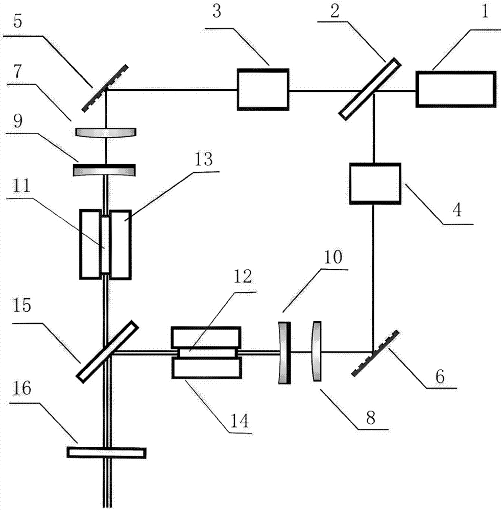
[0026] A schematic structural diagram of a white light laser provided in this embodiment, see figure 1 As shown, it includes pump source 1, beam splitter 2, first adjustable attenuator 3, second adjustable attenuator 4, total reflection mirror 5, total reflection mirror 6, lens 7, lens 8, first rear cavity Mirror 9, second rear cavity mirror 10, first laser crystal 11, second laser crystal 12, first heat dissipation copper block 13, second heat dissipation ...


PUM


Abstract

The invention relates to a white laser. The laser comprises a pumping source, a first resonant cavity and a second resonant cavity; the pump source is a blue light semiconductor laser; a pumping lightof the pumping source transmitted by a beam splitter sequentially passes through a first adjustable attenuator, a first total reflection mirror and a first lens and is incident on the first resonantcavity, and a first laser crystal is pumped to generate a red light; a pumping light of the pumping source reflected by the beam splitter sequentially passes through a second adjustable attenuator, asecond total reflection mirror and a second lens and is incident on the second resonant cavity, and a second laser crystal is pumped to generate a green light; the red light, the green light, a blue light which is incident on the first resonant cavity from the pumping source and not subjected to start-oscillation and a blue light which is incident on the second resonant cavity from the pumping source and not subjected to start-oscillation are outputted out of the cavities through a dichroic mirror and a laser output laser to be mixed to form a white light. According to the white laser, power of the pumping lights incident on the two resonant cavities is adjusted through the two adjustable attenuators respectively, so that power ratio of the red light to the green light is controlled to achieve adjusting of the outputted white light spectrum.

Description

technical field [0001] The invention relates to the fields of laser illumination and laser display, in particular to a white light laser. Background technique [0002] With the advancement of science and technology and the rapid development of laser technology, lasers have been widely used in communication, medical treatment, machining, weapons, lighting and other fields. Limited by the high monochromaticity of lasers, lasers mainly output monochromatic light. Of course, researchers have also made a lot of efforts and attempts in the field of white light laser research, and achieved good results. [0003] At present, the methods of using laser technology to generate white light mainly include: (1) using multiple discrete lasers to synthesize white light, this method requires multiple devices, and the whole system is inconvenient to move and difficult to operate; (2) using high optical power The nonlinear response of the material produces lasers of different colors, which a...

Claims


Application Information

Patent Timeline
IPC IPC(8): H01S3/06H01S3/0941H01S3/10
CPCH01S3/0602H01S3/0941H01S3/10084Y02B20/00
Inventor 陈旭东昌成成林志立
Owner HUAQIAO UNIVERSITY
Learn More