
Vacuum freeze drying device and method

A vacuum freeze-drying and vacuum chamber technology, applied in the direction of drying solid materials, drying solid materials without heating, drying, etc., can solve the problems of long freeze-drying cycle and large energy consumption of deicing on the surface of the condensing device, and reduce water and electricity. Energy consumption, the effect of shortening the cycle

Pending Publication Date: 2018-05-04
SHANGHAI PUDONG FREEZE DRYER EQUIP
View PDF9 Cites 1 Cited by
  • Summary
  • Abstract
  • Description
  • Claims
  • Application Information

AI Technical Summary

Problems solved by technology

[0004] The purpose of the present invention is to provide a vacuum freeze-drying device, which can solve the problems of long freeze-drying cycle and high energy consumption for deicing the surface of the condensing device in the prior art

Method used


Image

  • Vacuum freeze drying device and method
  • Vacuum freeze drying device and method

Examples


Embodiment 1

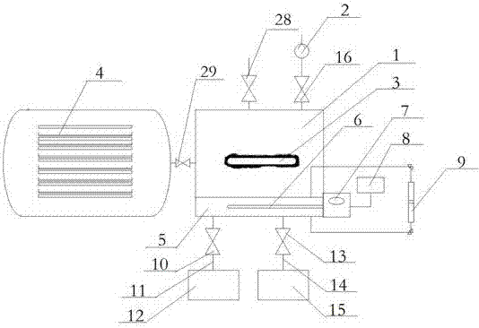
[0028] Such as figure 1 As shown, a vacuum freeze-drying device includes a vacuum chamber 1, the vacuum chamber 1 is connected to the material bin 4 through a pipeline, the pipeline is provided with an isolation valve 29, the material bin 4 is provided with a heater and a refrigerator, and the vacuum chamber 1 is connected to a vacuum pump Group 2 and the first re-pressure valve 28, a vacuum valve 16 is provided between the vacuum pump group 2 and the vacuum chamber 1, a condenser coil 3 is arranged inside the vacuum chamber 1, and the inside of the condenser coil 3 is filled with condensing agent, and the vacuum chamber 1 There is a water storage container 5 at the bottom, a temperature sensor and a liquid level sensor are installed in the water storage container 5, the temperature sensor is externally connected to a temperature display 7, the liquid level sensor is externally connected to a liquid level controller 9, and a part of the heating device is provided inside the wat...

Embodiment 2

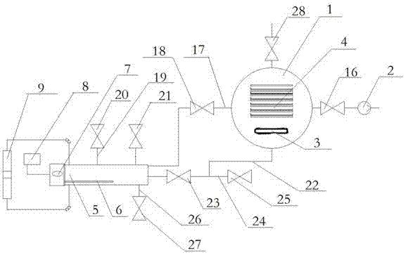
[0036] Such as figure 2 As shown, a vacuum freeze-drying device includes a vacuum chamber 1, a material bin 4 is arranged inside the vacuum chamber 1, a heater and a refrigerator are arranged inside the material bin 4, and the vacuum chamber 1 is connected to the vacuum pump group 2 and the first re-pressure valve 28. A vacuum valve 16 is provided between the vacuum chamber 1 and the vacuum pump 2. A condenser coil 3 is provided inside the vacuum chamber 1. The condenser coil 3 is placed at the lower part of the material bin 4 and filled with a condensing agent. The vacuum chamber 1 Connect the external water storage container 5, the water storage container 5 is provided with a temperature sensor and a liquid level sensor, the temperature sensor is externally connected to a temperature display 7, the liquid level sensor is externally connected to a liquid level controller 9, and the water storage container 5 is provided with a partial heating device 6, The heating device 6 is...


PUM


Abstract

The invention discloses a vacuum freeze drying device. The vacuum freeze drying device comprises a vacuum chamber, a material bin, a condenser coil, a water storage container and a heating device; thevacuum chamber respectively communicates with the material bin and the water storage container; the condenser coil is arranged in the vacuum chamber; a liquid level sensor is arranged in the water storage container, and is externally connected with a liquid level controller; a heating end of the heating device is positioned in the water storage container; a temperature sensor is externally connected with a temperature displayer; and a heater and a refrigerator are arranged in the material bin. The ice melting process is performed in a vacuum container before product drying by one hour; when the product drying process is finished, the ice melting process is also finished; the vacuum freeze drying device can be directly used in the next phase, so that the product freeze drying period is shortened; and in the ice melting process, vaporized heat of water under vacuum conditions is used for providing heat to ice layers, so that water and electricity energy consumption caused by hot water spraying or hot water dipping is greatly reduced.

Description

technical field [0001] The invention relates to the technical field of vacuum freeze-drying, in particular to a vacuum freeze-drying device and method. Background technique [0002] Vacuum freeze-drying technology is to pre-freeze the liquid product at 5-10°C below the eutectic point temperature or vacuum freeze it under vacuum, and then make the ice crystals in the frozen product obtain the latent heat of sublimation converted into water vapor under vacuum conditions, so that To achieve the purpose of removing more than 95% of the moisture in the product. The sublimated water vapor is calculated at 1kg / (m 2 .h) The volume of water vapor produced by the meter is very large at a pressure of about 100Pa, about 10 6 In this way, more than 30 vacuum pumps are needed, which is actually unrealistic. On the one hand, the combination of many vacuum pumps consumes a lot of power. Therefore, the existing vacuum freezing device generally uses a low-temperature condensing device to c...

Claims


Application Information

Patent Timeline
Patent Type & Authority Applications(China)
IPC IPC(8): F26B5/06F25B47/00
CPCF25B47/00F26B5/06
Inventor 黄良瑾张耀平
Owner SHANGHAI PUDONG FREEZE DRYER EQUIP
Learn More