Efficient axial centrifugal fan

A centrifugal fan, high-efficiency technology, used in mechanical equipment, machines/engines, liquid fuel engines, etc., can solve the problem that reliability and service life do not meet user requirements, structural performance does not meet design requirements, and airflow velocity gradient does not meet the requirements. Equalize the problem to achieve the effect of improving head and efficiency, reducing weight, impeller flatness and end runout

Pending Publication Date: 2018-05-04
ZHUZHOU LINCE GRP
View PDF13 Cites 1 Cited by
  • Summary
  • Abstract
  • Description
  • Claims
  • Application Information

AI Technical Summary

Problems solved by technology

[0002] At present, the aerodynamic and structural performance of ordinary axial centrifugal fans cannot meet the design requirements, the airflow velocity gradient is uneven, the guide vane vibrates greatly, the overall weight is heavy, the energy consumption is large, and the reliability and service life cannot meet the user's requirements.

Method used


Image

  • Efficient axial centrifugal fan
  • Efficient axial centrifugal fan
  • Efficient axial centrifugal fan

Examples


Embodiment Construction

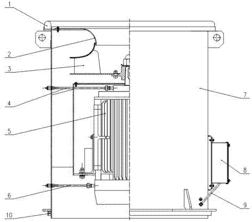
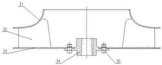
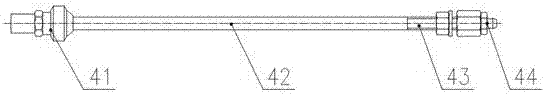
[0020] refer to figure 1 , figure 2 , image 3 with Figure 4 , a high-efficiency axial centrifugal fan, including an upper sealing ring 1, an air inlet duct 2, an impeller 3, a front-end filling pipe 4, a motor 5, a rear-end filling pipe 6, an air cylinder 7, a junction box 8, a grounding wire 9, The lower sealing ring 10 is characterized in that:

[0021] The air cylinder 7 is provided with an upper sealing ring installation ring 71, lifting lug 72, outer cylinder 73, guide vane 74, inner cylinder 75, lower sealing ring installation ring 76, junction box mounting seat 77, reinforcing rib 78 and grounding Nut 79, wherein, the upper sealing ring installation ring 71 on the fan cylinder 7 and the lower sealing ring installation ring 76 are respectively provided with the upper sealing ring 1 and the lower sealing ring 10, which effectively reduces the vibration and impact from the car body, and at the same time The vibration of the fan itself is also blocked from propagatin...


PUM


Abstract

The invention relates to an efficient axial centrifugal fan. The efficient axial centrifugal fan comprises an upper sealing ring, a lower sealing ring, an air inlet duct, an impeller, a front-end oilfilling pipe, a motor, a rear-end oil filling pipe, an air cylinder, a connecting box and a ground lead. An impeller of the fan is of a backward type centrifugal impeller structure. A blade is of a straight plate blade profile structure. A front wheel disc, a rear wheel disc and a wheel core are connected through self-plugging rivets, the impeller flatness and end jump of the fan are better by theadoption of a riveting manner, and the impeller is more attractive in appearance; and a pneumatic structure is more optimized, the weight of the fan is reduced on the premise of guaranteeing the pneumatic performance and the structure performance of the fan, and the process is simple. The excellent pneumatic structure of the impeller and the pneumatic structure of the air cylinder are optimally matched so that the efficiency of the fan can be improved greatly. A guide vane of the fan is in a front end inclined form, the non-uniform airflow velocity gradient can be well treated, the vibrationproblem is solved, and the welding strength of the fan is improved; and lubricating grease is regularly added to a motor bearing by the adoption of the oil pipes for both the front portion and the rear portion of the motor, the lubricating effect of the bearing is guaranteed, the reliability of the fan is improved, and the service life of the fan is prolonged.

Description

technical field [0001] The invention relates to a high-efficiency axial centrifugal fan, which is a structurally improved high-efficiency axial centrifugal fan. Background technique [0002] At present, the aerodynamic and structural performance of ordinary axial centrifugal fans cannot meet the design requirements, the airflow velocity gradient is uneven, the guide vane vibrates greatly, the overall weight is heavy, the energy consumption is large, and the reliability and service life cannot meet the user's requirements. Contents of the invention [0003] The purpose of the present invention is to overcome the deficiencies and defects of the prior art, and provide a high-efficiency axial centrifugal fan with good aerodynamic and structural performance, uniform airflow velocity gradient, light overall weight, low energy consumption, high reliability and long service life . [0004] The technical solution of the present invention: a high-efficiency axial centrifugal fan, i...

Claims


Application Information

Patent Timeline
Patent Type & Authority Applications(China)
IPC IPC(8): F04D25/08F04D29/063F04D29/28F04D29/30F04D29/42F04D29/44F04D29/66
CPCF04D25/08F04D29/063F04D29/284F04D29/30F04D29/4206F04D29/444F04D29/668
Inventor 刘梦安詹腾谭发容
Owner ZHUZHOU LINCE GRP
Why Eureka
Try Eureka